I was designing for some motor applications earlier in the week and had to select a freewheeling diode for the circuit. So, I thought it might be a good time to cover that here. Freewheeling or Flyback or antiparallel (there are more aliases as people call it whatever they want) diodes are normal diodes used uniquely in a circuit. It’s connected right across an inductive load like a motor.
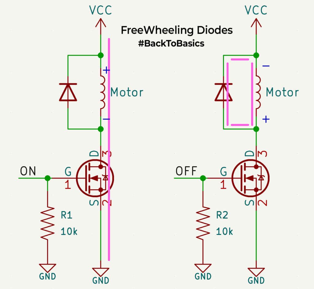
So how does it help? Take the example shown in the image, there is a motor that is turned ON/OFF with a MOSFET. During the ON cycle, the current flows through the inductor/coil of the motor, and the motor rotates. Now let’s turn OFF the MOSFET, the current flow from the power source suddenly stops. From Inductor 101, we know that an inductor doesn’t like abrupt changes in current and it has stored energy( in its coils(magnetic fields) during the ON cycle. Since the circuit is open, it has no way to discharge that energy, which means there will be a large spike in voltage at the inductor node, potentially damaging the MOSFET.
To avoid this, we place a diode in the opposite direction across the inductor which opens a new path for the energized inductor to discharge on its ON. In normal operation, since the diode is reverse-biased, it doesn’t affect the circuit.
How do you select one for your design? Choose a Schottky diode as it is faster to react. Find the maximum current passing through the motor/inductor during normal operation, your diode’s average forward should be much higher than this value. I personally use times x2 as a safety margin(if I am not penny-pinching on BOM prices). The maximum reverse voltage rating of the diode should be again higher by a factor of 2 compared to the normal working voltage applied across your motor. That’s basically it. You can select a freewheeling diode keeping these in mind and it will work just fine.
Hope that was helpful.