Back to Basics: LEDs: Part 7: Analog Dimming

Analog Dimming

We looked into PWM dimming last time. Analog dimming, unlike its digital counterpart, involves manipulating the continuous current flowing through LEDs to adjust their brightness. While PWM dimming regulates the on-off cycles of LEDs, analog dimming offers a seamless, gradual, and continuous adjustment. The main benefit of analog dimming is the fact that it offers flicker-free LEDs, this is why it’s one more preferred approach for photography applications. You don’t have the hassle of shutter speed sync as in PWM dimming.

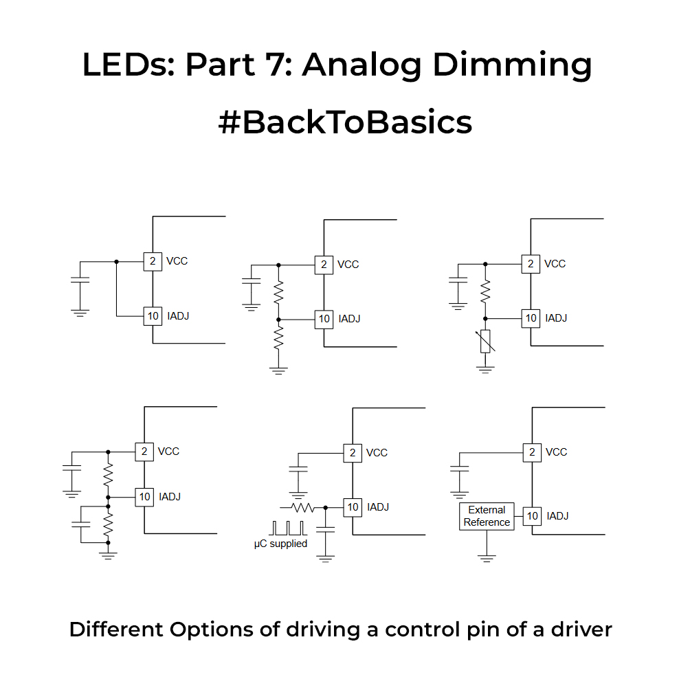
Analog dimming is supported by certain LED drivers where you have a dedicated pin that is driven by an analog voltage from a microcontroller or a DC source. These drivers usually have a linear range of operation wherein increasing the voltage on the control pin will increase the current through the LEDs. At the extremities of the linear region you may have sharp jumps in brightness, so always take care of the region of operation if you want a constant light output. BTW if you don’t have variable DAC output to drive the analog pin, you can generate a PWM signal and pass that through a low pass filter whose average output can then be fed to the Control pin.

Since these drivers need to be driven by small analog values, it’s usually recommended to have the driver relatively near to the microcontroller generating the voltage to avoid losses in transmission, esp. in the cases that LEDs are placed in a separate board and you are connecting them with long wires. One main disadvantage of analog dimming is its lower dimming ratio and also the colour shift in the light output because the current is getting changed. So if you want the colour temperature to be constant through its range, this would not be the right topology for you. Choose wisely.

If you liked the post, Share it with your friends!

Back to Basics: LEDs: Part 6: PWM Dimming

PWM Dimming LEDs
PWM Dimming LEDs

One of the key ways of dimming LEDs is via PWM dimming. At its core, PWM dimming involves rapidly turning LEDs on and off at a specific frequency. The ON time aka the duty cycle of the PWM signal, determines the average current through the LED. Usually, the LED driver is driven by a microcontroller’s PWM pin. The microcontroller can control three main parameters of the PWM signal. First is the duty cycle or the ON time. Higher the ON time, more the current, brighter the LED intensity.

Second is the frequency of the PWM signal which determines the rise and fall time of the LED current at the output of the driver. You will mostly find a ripple current at the output of the LEDs in an approx triangular fashion. If the frequency is excessively high, the LED might not reach its peak current, leading to diminished dimming/contrast ratios. If any frequency below 150Hz(approx) is used, the human eye will be able to pickup the flickering of the LEDs and cannot be used in lighting use cases. Yet, in specialized scenarios such as using LEDs for high-speed camera imaging(lower exposure rate), flickering becomes visible if a lower rate is used. Another way to mitigate the flicker is to sync the shutter speed of the camera with the LED PWM frequency although this option is often limited to scientific cameras. Hence, your choice of PWM frequency should align with your application’s demands.

Thirdly, let’s talk about PWM resolution, dictating dimming precision or how finely you can control brightness levels. An 8-bit resolution offers 256 levels of brightness, while a 10-bit gives you 1024 levels. PWM resolution is often inversely related to PWM frequency for most microcontrollers. This means you can have a high PWM frequency with lower resolution and vice versa, finding the right equilibrium is key.

In essence, mastering PWM dimming involves this intricate dance between duty cycle, frequency, and resolution, each parameter finely tuned to cater to the unique demands of your application.

If you liked the post, Share it with your friends!
1 5 6 7 8 9 34