Advanced: Glass Core Substrates

A couple of months ago Intel in an event introduced a cool new tech in the chip packaging domain, which I think is pretty cool. When IC chips get manufactured, they get placed on a substrate which allows chips to talk to other chips. These can be memory, GPU, or with your PC motherboard. The faster you can talk between these units, better the performance. We currently use organic substrates similar to the FR4 materials that you use in your circuit PCBs.


Intel is proposing a new glass core substrate that aims to outperform existing organic substrates, thereby facilitating larger chips on a single substrate. The glass core substrate isn’t an entire glass replacement; it augments the organic material at the core. Metal redistribution layers (RDLs), which allow one part of the chip to talk to another part, are placed on both sides of the glass substrate. The key advantage of glass lies in superior mechanical strength and its being extremely smooth as a surface. Not like the woven fibers in PCBs(Search for microscopic images of your PCB substrate, you can see mountains and valleys). Glass can withstand higher temperatures during packaging and reducing warping. It can transfer data at an extremely high speed with very little losses.

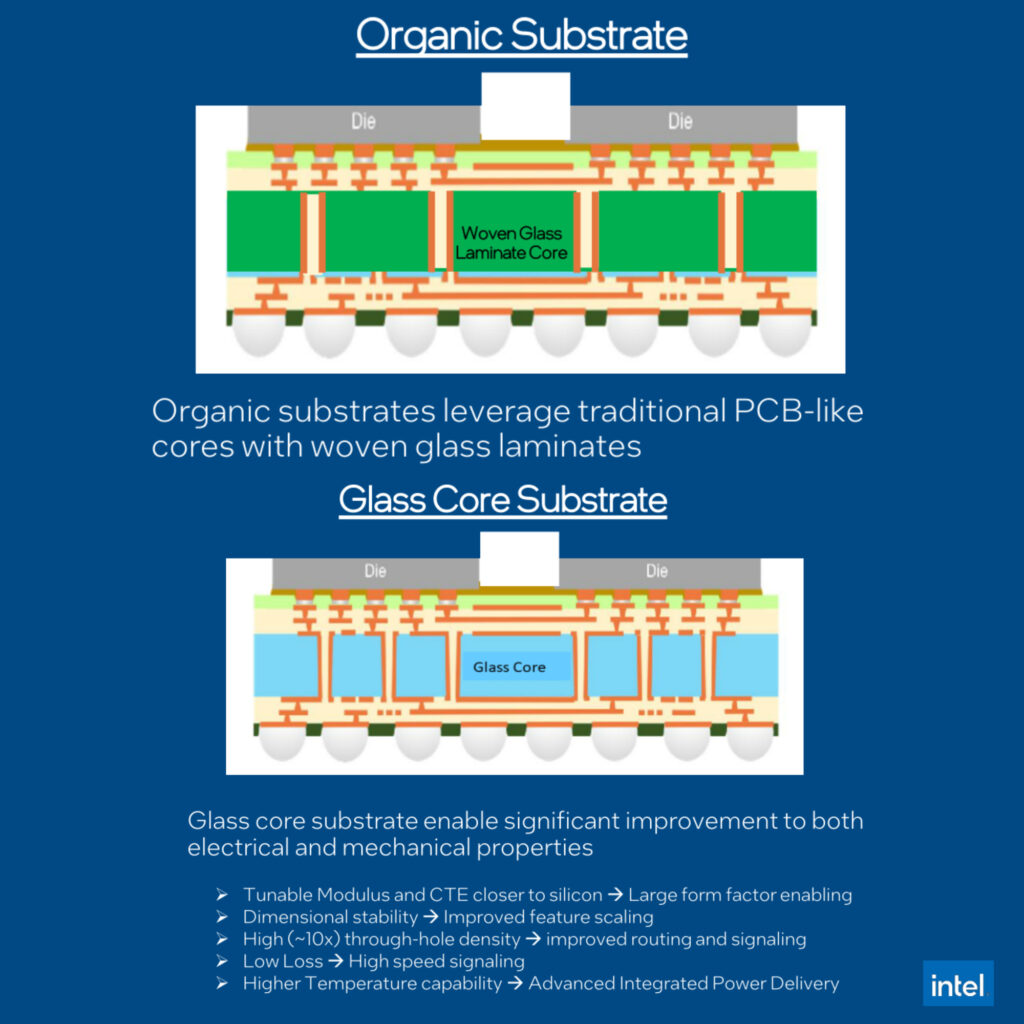
Glass core substrates boast better electrical performance, with Through-Glass Vias (TGVs) similar to your PCB vias but with a very high-density spacing of around 100um between vias. This translates into the ability to accommodate 50% more dies on a chip, a substantial leap in chip density.The transition to glass core substrates will begin later this decade, starting with high-end HPC and AI chips. The limiting factor is its cost. But it’s bound to reduce in price as the tech matures. Likely glass is one of the hottest candidates in the material space. Do check out Project Silica from Microsoft which uses glass to store data for potentially eternal storage of 10,000+ yrs.

If you liked the post, Share it with your friends!

Back to Basics: LEDs: Part 11: Light Pipes

One of the harder problems I face when I design products with LEDs is how to get this light to the user on the product surface, esp. the indicator LEDs. How do you make them look good in a product? Enter Light Pipes. These are fundamentally mechanical parts made usually of transparent acrylic or polycarbonate to guide light from your LED source to the product surface. They operate based on Total Internal Reflection. Light enters at an angle greater than the critical angle, undergoes multiple internal reflections, and exits on the other side.

LightPipes come in two types, Rigid & flexible. Rigid ones are common in consumer products where the LED’s position is fixed, and the path to the surface is relatively straight. It can be mounted directly on a PCB in a straight line, or at a 90-degree angle in cases where a straight path isn’t feasible (Check images). For 90-degree LightPipes, a slight turn radius is advisable to minimize light losses. On the other hand, Flexible light pipes, typically crafted from optical fibers, can be bent into various shapes to achieve the desired light output.

The important consideration point is the light entering point between the LED and the pipe. Your goal is to ensure maximum light enters the pipe and minimize leakages. You can do that by having an opaque coupler or by reducing the distance between the LED and pipe to an absolute minimum(but not touching). Usually width of the input of the light pipe should be wider than the beam angle of the LEDs, so for these applications always prefer using LEDs with a lower beam angle for larger light coupling.

And there you have it! Wrapping up this LED series. It’s been fun. I’ve tried to cover all things LED-related, making it as enjoyable and informative for you as it was for me putting it together. Hoping you loved it. If I missed anything, give me a shout. See you next week with something else.

If you liked the post, Share it with your friends!
1 2 3 4 21