Back to Basics: LEDs: Part 8: Colour Rendering Index (CRI)

CRI
CRI

Today, let’s discuss a key aspect of LED lighting – the Colour Rendering Index or CRI. Imagine this: you’ve carefully selected your LED lights for let’s say a photography application, and yet, the colours in your space seem slightly off. This discrepancy might just be due to the CRI.

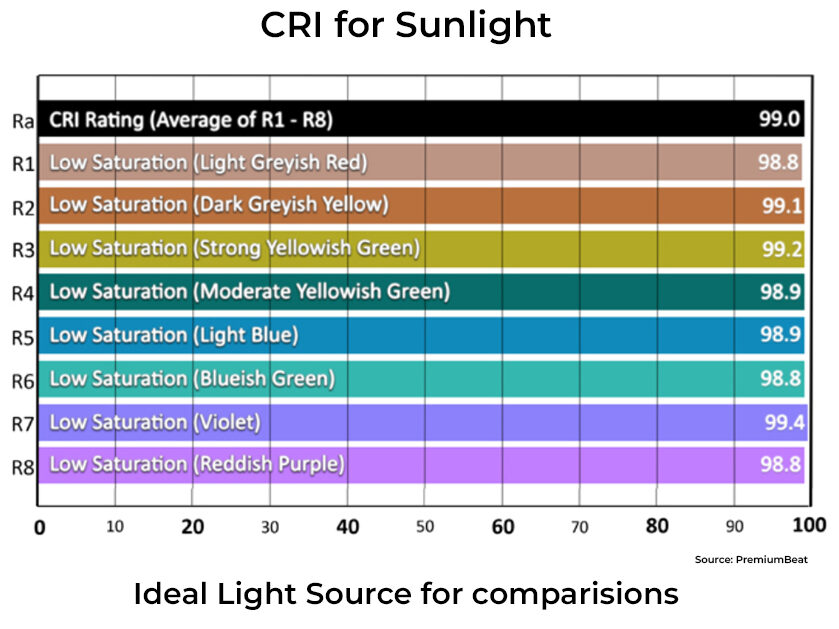
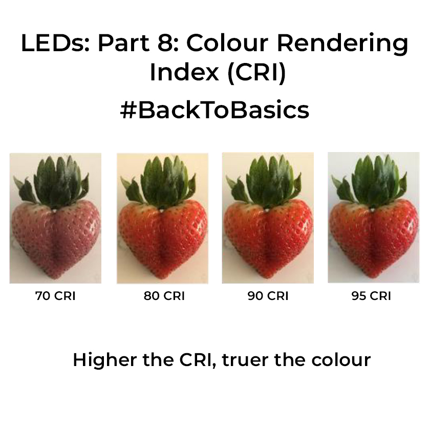
CRI essentially gauges how accurately a light source represents colours compared to natural daylight. Measured on a scale from 0 to 100, a higher CRI signifies truer colours. CRI is determined by assessing how a light source influences eight standard colour samples(called R1-R8), and comparing it to a reference source like tungsten or daylight. These samples represent a range of colours in the spectrum. Usually, a CRI of 90+ represents great colour reproduction. Check images for a comparison.

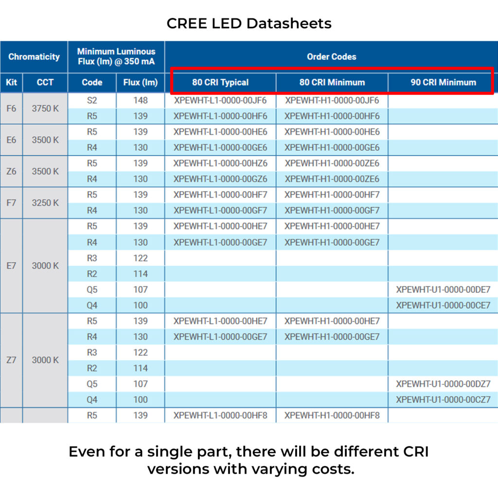
So What should you keep in mind while selecting LEDs for colour-sensitive application? Go through the datasheet thoroughly. Even for a particular part number of an LED, there will be various bins or subparts catering to different CRIs. Select part numbers based on that. A basic rule of thumb is to get something with a CRI value over 90 for these applications. Higher the CRI, higher the price. In certain specialized applications, additional colour scales like R9-R15, known as extended CRI, are used to further assess light quality. However, these details are usually absent in standard datasheets, except for highly customized LED solutions. CRI in LED selection is one of those decisions in life – you’ll know if you need it! ?

If you liked the post, Share it with your friends!

Back to Basics: LEDs: Part 7: Analog Dimming

Analog Dimming

We looked into PWM dimming last time. Analog dimming, unlike its digital counterpart, involves manipulating the continuous current flowing through LEDs to adjust their brightness. While PWM dimming regulates the on-off cycles of LEDs, analog dimming offers a seamless, gradual, and continuous adjustment. The main benefit of analog dimming is the fact that it offers flicker-free LEDs, this is why it’s one more preferred approach for photography applications. You don’t have the hassle of shutter speed sync as in PWM dimming.

Analog dimming is supported by certain LED drivers where you have a dedicated pin that is driven by an analog voltage from a microcontroller or a DC source. These drivers usually have a linear range of operation wherein increasing the voltage on the control pin will increase the current through the LEDs. At the extremities of the linear region you may have sharp jumps in brightness, so always take care of the region of operation if you want a constant light output. BTW if you don’t have variable DAC output to drive the analog pin, you can generate a PWM signal and pass that through a low pass filter whose average output can then be fed to the Control pin.

Since these drivers need to be driven by small analog values, it’s usually recommended to have the driver relatively near to the microcontroller generating the voltage to avoid losses in transmission, esp. in the cases that LEDs are placed in a separate board and you are connecting them with long wires. One main disadvantage of analog dimming is its lower dimming ratio and also the colour shift in the light output because the current is getting changed. So if you want the colour temperature to be constant through its range, this would not be the right topology for you. Choose wisely.

If you liked the post, Share it with your friends!
1 3 4 5 6 7 52