Back to Basics: Battery Strap Fuses

Battery strap PTCs, or Positive Temperature Coefficient devices(a fancy way of saying its resistance increases with an increase in temperature), are components designed to protect batteries and associated circuits from overcurrent conditions. These are relatively unknown to folks outside the battery industry. Please don’t mistake them for the SMD fuses we fuse while designing PCBs for protection. Although they work on similar principles, the strap-ones are uniquely thin-shaped and attached directly to the batteries.

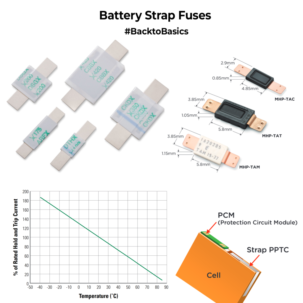
Battery strap PTCs act as self-resetting fuses. When an overcurrent condition occurs, the PTC heats up and its resistance rises dramatically, reducing the current flowing through it. This effectively limits the current to a safe level. Once the fault or overcurrent condition is removed, the PTC cools down, and its resistance decreases, allowing normal current flow to resume. Like all fuses, it will have a specific hold current(current allowed to pass in normal operation) and a trip current(current at which the device goes into high resistance mode). One major thing to keep in mind is that these hold/trip currents are temp-specific; as temperature increases, these values fall, and they will trip faster. In a way, it’s a nice thing because when the battery shorts, the temp shoots up and it reaches the trip point faster, but make sure it doesn’t trip in normal ambient or when the battery is getting charged(as the temp increases)

These fuses are usually spot welded or crimped on the battery terminals directly. It forms a great first line of protection in large battery packs and plays a crucial role in reliable and long-lasting battery solutions.

Have you ever used them in a project? How was your experience with it?

If you liked the post, Share it with your friends!

Back to Basics: Freewheeling diode and How to choose one

I was designing for some motor applications earlier in the week and had to select a freewheeling diode for the circuit. So, I thought it might be a good time to cover that here. Freewheeling or Flyback or antiparallel (there are more aliases as people call it whatever they want) diodes are normal diodes used uniquely in a circuit. It’s connected right across an inductive load like a motor.

So how does it help? Take the example shown in the image, there is a motor that is turned ON/OFF with a MOSFET. During the ON cycle, the current flows through the inductor/coil of the motor, and the motor rotates. Now let’s turn OFF the MOSFET, the current flow from the power source suddenly stops. From Inductor 101, we know that an inductor doesn’t like abrupt changes in current and it has stored energy( in its coils(magnetic fields) during the ON cycle. Since the circuit is open, it has no way to discharge that energy, which means there will be a large spike in voltage at the inductor node, potentially damaging the MOSFET.

To avoid this, we place a diode in the opposite direction across the inductor which opens a new path for the energized inductor to discharge on its ON. In normal operation, since the diode is reverse-biased, it doesn’t affect the circuit.

How do you select one for your design? Choose a Schottky diode as it is faster to react. Find the maximum current passing through the motor/inductor during normal operation, your diode’s average forward should be much higher than this value. I personally use times x2 as a safety margin(if I am not penny-pinching on BOM prices). The maximum reverse voltage rating of the diode should be again higher by a factor of 2 compared to the normal working voltage applied across your motor. That’s basically it. You can select a freewheeling diode keeping these in mind and it will work just fine.

Hope that was helpful.

If you liked the post, Share it with your friends!
1 2 3 4 76