Prologue
(Skip this section, take me to the cool stuff)
Last week, guys over at BoltIoT gave me one of their hardware products (Currently live & funded on Kickstarter), a Bolt WiFi Module and a starter kit, to get my feedback. They wanted me to try it out and see if I can make a project out of it. I told them that, if I were to review it, they can’t just expect me to write only good stuff about it, I would have to write about the other half as well. BoltIoT was cool with it and said that they were genuinely looking for an honest feedback before they ship the product to their Kickstarter customers.
So last Saturday morning, I decided to give the product a full rundown. The device is a development platform aimed at the maker community at large. So if I had to do a proper review of the product, I needed to do a project with it and then see how good or bad it is. The constraints I set myself for the review project were,
- I should be able do a project right from the ideation phase to finishing it, to documenting the entire process over a weekend. i.e. It shouldn’t be too complex a project, as I am dealing with a totally new platform which I haven’t worked with before.
- I should only use stuff which are there in my home-lab setup. i.e. I shouldn’t have to go out to buy anything from outside for this project.(This usually helps me to focus and force me to work with the stuff I have)
- Try your best not to replicate any common projects out there like home automation, lighting automation etc.
- Product solution should benefit me(as well as others) and ideally I should want to use it on a regular basis.
Problem Statement
With the above constraints in mind, I started on the ideation phase on a Saturday morning. I went about each room in my flat to see if I can get inspiration from any of the items in the rooms. Alas, I couldn’t find a damn project to do. Exhausted with all that mind-workout in the morning, I slumped into my work chair. That’s when it hit me. Why don’t I do something with my work chair?
Well, I spend most of my days in this chair working on my PC or on my electronics workbench. This chair(It’s a nice one BTW. High Back and Super Comfy) is probably the most used item in my home after my PC. So any modification to this, is definitely going to help me in some fashion.
I have a problem, when I am in the work mode, I usually loose track of time. In the early engineering days of ACPAD when we working on releasing our product, I used sit on a problem for days-on-end. I am known among my co-founders for not leaving my flat for a long time. There was a time, when I actually didn’t set foot out of my flat for a week and the only moving about I did was to go to bathroom/shower/bed and to walk upto the front door to take the food delivery from the delivery boy. Well, that lifestyle did affect my health last year. But I managed to pull through. Although the workload has eased a bit since we shipped our product, my working style didn’t undergo a major change. That had to change.
I wanted this chair to tell me if I was sitting on it for a long time and alert me to take break and move about. Since most of my time while I am on this chair, I am working on the PC, I wanted an alert to nag me enough to stop doing whatever I am doing and to take a walk.
So its decided then, I am going to make my chair “smart” by putting a chip in it… (Cliché… 😛 )
Hardware
I thought through the system block implementation and was able to arrive at what all was needed for this project. A sensor to sense if I am sitting on the chair and a device which could push the data to cloud and alert me. For sensors, I had the choice of using load cells and Force Sensitive Resistors(I had both of them in my sensor kit at home). I decided to go ahead with Force Sensitive Resistor(FSR) because it’s easier to work with than load cells.
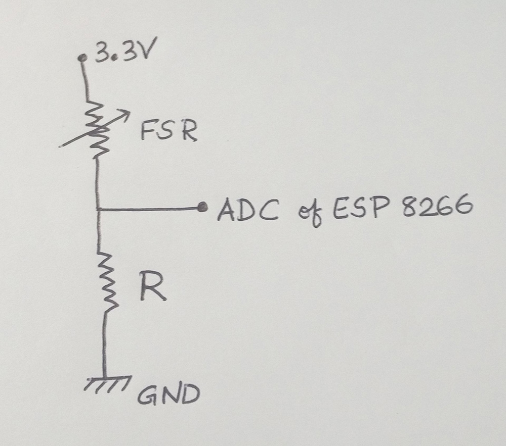
Force Sensitive Resistors(FSR), for the uninitiated, are a two terminal, variable resistor whose resistance varies with the applied force. More force you apply, lower is the resistance. Connect one of the terminals to a voltage like 3.3V and other end to a pull down resistor, you will have a variable voltage in the voltage divider network, which can be measured with an ADC.
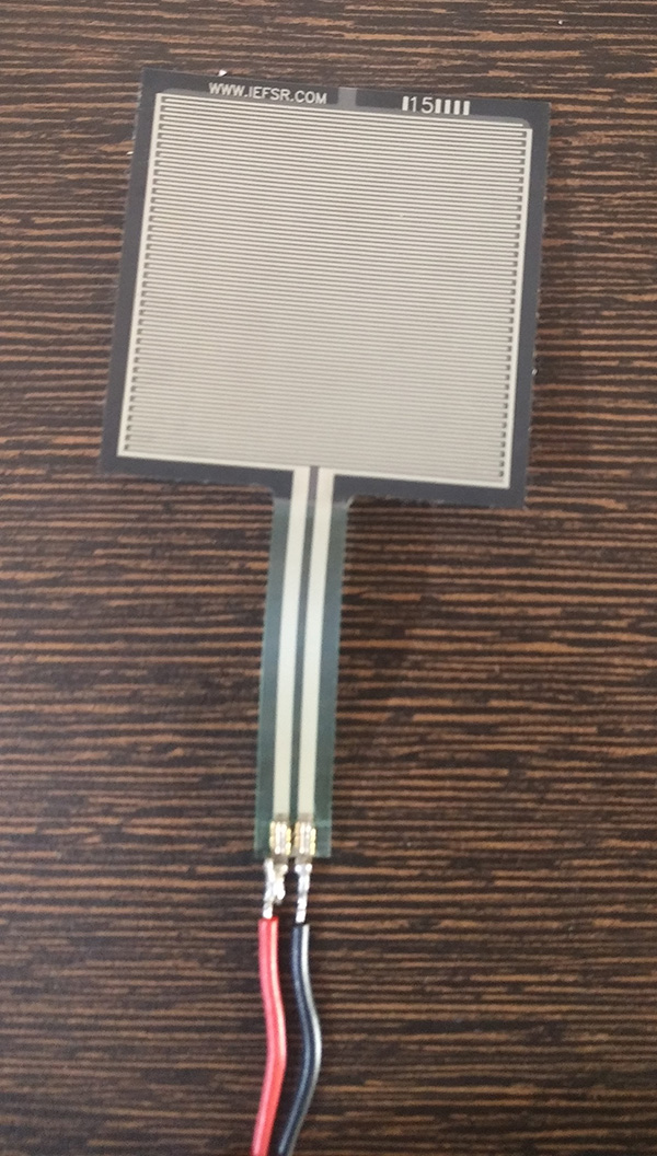
A Force Sensor
First thing you need to do is to figure out a spot where you can attach the FSR in the bottom section of the chair. I had to remove the screws(Ikea type) from the bottom of the chair and slide the force sensor in tightly so that there is a firm contact when someone sits on the chair. You may want to stick a foam on top of the sensor to ease the force distribution on the sensor. Solder wires on the sensor(Be careful as its tricky and the plastic can melt at soldering temperature. So be quick during soldering) and connect the pull-down resistor on one end of the sensor.
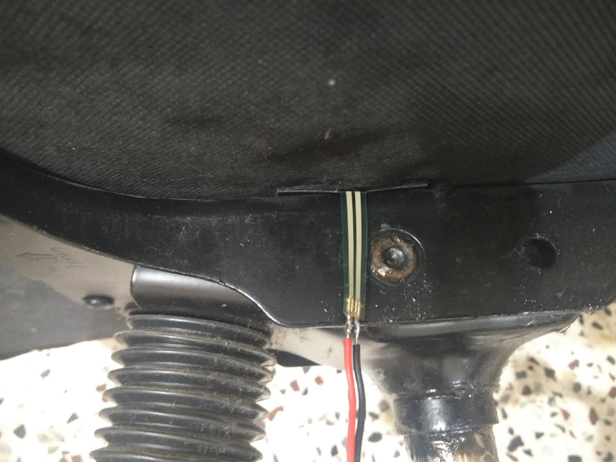 Force Sensor below the chair
Value of the resistor R need to be calculated to maximize the variation of the voltage at the ADC input. For this, attach the two leads of the sensor to a multimeter in resistance mode and measure the resistance Rmin, when you are sitting on the chair and Rmax, when you are not sitting on the chair. For the maximum dynamic voltage variation over the resistance range, the ideal pull down resistance value R = √(Rmin * Rmax) (I will put out the derivation for this formula on a later date as it involves some amount of math). Calculate the resistance accordingly and solder it to your sensor.
Now that we have our sensor section figured out. Let’s get on with the Bolt Platform.
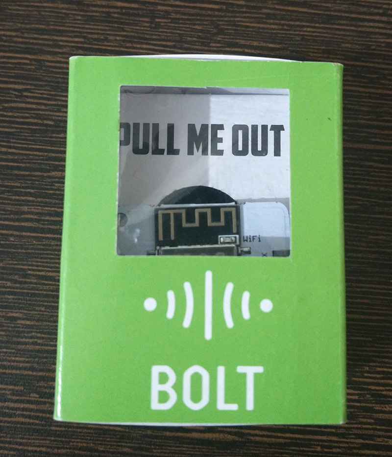
Unboxing
The device from BoltIoT came in a cute packaging.
It contained the following (It’s selling for $12 on their Kickstarter)
- Bolt WiFi Module
- IR Sensor Module
- Light Dependent resistors
- Push Button Switch
- Piezo Buzzer
- 2 x LEDs
- 2 x Resistors
- Couple of Jumper wires
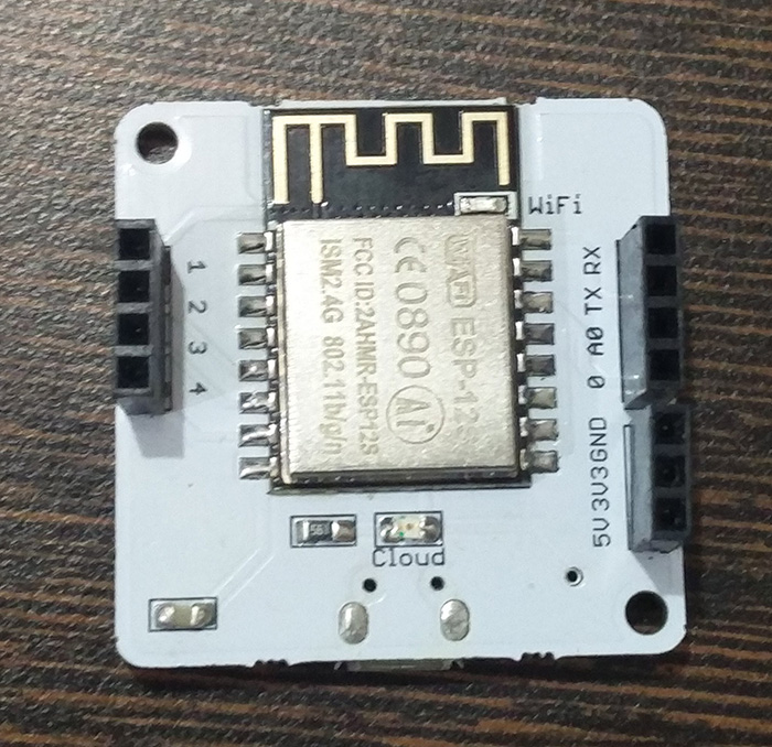
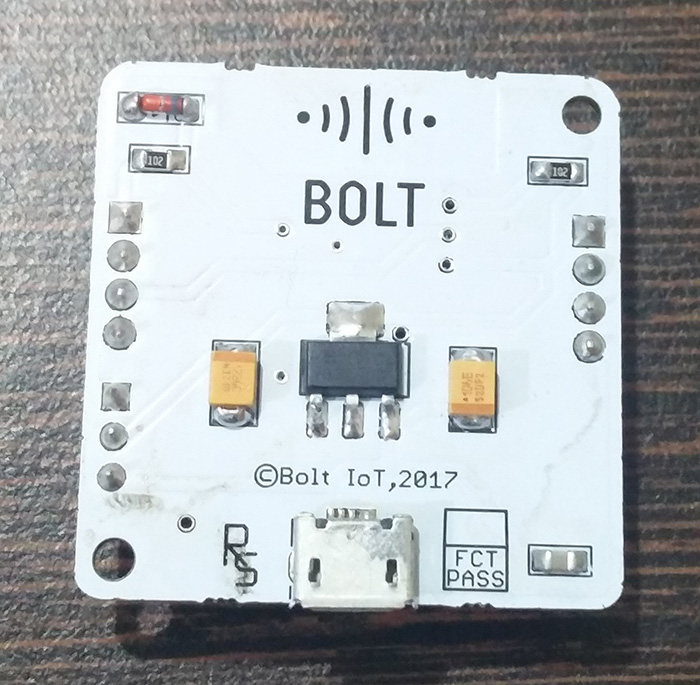
What we are interested in is the Bolt WiFi Module.
It’s an ESP-12S Breakout board(FCC Documents) based on ExpressIf’s popular ESP8266 WiFi IC. Module has a Micro USB port for 5V power supply and a LM1117 regulator to regulate it down to 3.3V. It has a couple of LEDs on top of the board for status indication. Manufacturing and soldering quality seems to be reasonably good.
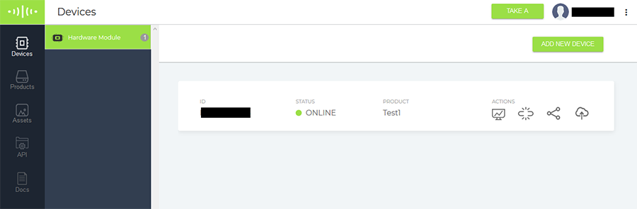
To get started with the device. You need to register an account on https://cloud.boltiot.com/register/ and download an app for it on your mobile(Both Android and iOS are supported). Power ON the device by plugging it in to a 5V USB supply(like a Powerbank) and follow the instructions in their Quickstart guide. It’s a breeze to setup and pair the device. I was able to get it up and running in 20mins. On the app, it will ask for your WiFi SSID and password which the device needs to connect to. Once the device is registered, you can see the status of the device on your Bolt Cloud Interface on your browser.
We need to connect the one end of the sensor to the 3.3V pin on the board and the other end to the ADC of the ESP-12S Module. The ADC on ESP8266 is a 10bit resolution ADC with a voltage range of 0-1V, i.e. 1V corresponds to a digital value of 1023 (2^10 – 1) and 0V corresponds to a digital value of 0. Just make sure that the resistances chosen are such that the voltage across the resistor, R is always in 0-1V range, else you will get a saturated value on your ADC(Potentially might damage it too).
On the Bolt cloud front, do a product setup in which pin A0 is selected. (Just follow the LDR example in the quick start guide)

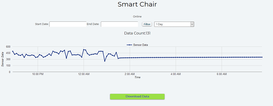
Once the device is linked and the product is setup, you can see the data taken from the sensor is pushed to the cloud and is put out in the form of a line graph. There is a problem with the interface here, the data from the device gets updated only every 5mins. I mailed Bolt Team about this and they mentioned it was rate limited to 5mins. But there is work around for it, if you want a faster data push rate, just hit the Deploy Configuration button on the product page so that data is pulled from the device and pushed to the cloud every time Deploy Configuration is pressed. You can use this as a work around to test the raw data stream coming from the device.
Please note, with APIs the data push rate is not throttled.
Post Edit: Apparently data push rate is not throttled for beta testers. They might put a daily API call limit for users. 🙁
If you are able to get the data on the cloud then it’s a success so far. Now we need to make decisions and trigger events based on this data. For that, I am going to use a platform known as Node Red.
Software: Node Red
To be honest, I haven’t used Node Red till this project. When I checked out the Bolt’s examples online ([1],[2]), I found that they were using it, so I should probably give it a try too. I was a bit skeptical at first, but boy, it’s a great tool.
Node Red is an open source, visual, GUI based(drag-and-drop-blocks type) development tool from IBM for bringing together all hardware and APIs in the IoT domain. It works from your browser. I will give you a brief intro, how to install and get started on it for Windows OS(Mac and Linux users have an even simpler process).
Installation
First of all, download and install Node.js from here, depending on your OS configuration(64bit or 32bit). Now open up the Command prompt on your Windows(Power Shell in Windows 10) and type in the following
npm install -g –unsafe-perm node-red
It might take a couple of minutes to install. After that, in the Command prompt type in
node-red
to start the node-red server. There will be a line which shows up as
Server now running at http://127.0.0.1:1880/
which says everything is working the way it should. If you are having any issues, I would suggest checking out this video.
Now open up your browser and type in
http://127.0.0.1:1880/ OR http://localhost:1880
to access the Node Red GUI interface.
Before going ahead, I would highly suggest watching these two getting started videos([1],[2]) which will make your life so much simpler. Believe me, Node Red is well worth the time taken to learn it.
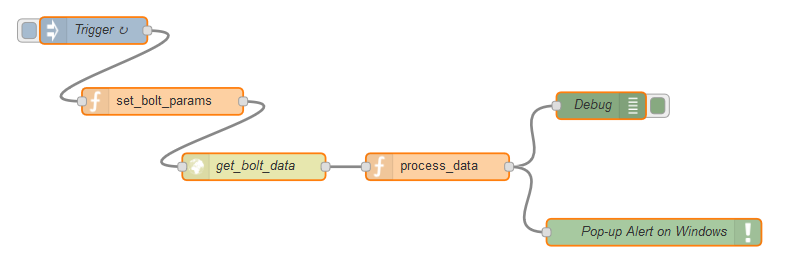
For our smart chair, I made a flow diagram which looks like
Before you can use my flow, you need to install a couple of things.
What I am trying to do is, to get the data from the Bolt device every 15 seconds and do some time based thresholding on it to figure out if I am sitting on my chair for more than an hour at a stretch or not. If I am, it needs to trigger an alert on my Windows PC.
For this you need to download the exe and install a free software called Growl from here. Growl is an event based triggering software. Its available for Mac and Linux as well. As their website says
“Put simply, Growl lets you know when things happen. Files finished downloading, friends came online, new email has arrived – Growl can let you know when any event occurs with a subtle notification. The rest of the time, Growl stays out of your way. “
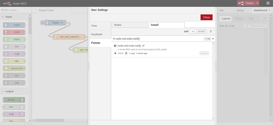
Now on your Node Red browser window, go to the menu on the top-right–>Manage Palette. In that, go to the Install tab and search for “node-red-node-notify” and install the package. This will add a notify section in the Nodes section on the left side of your main Node Red console. This is needed for triggering Growly from Node Red.
Now we need to install packages for Growl in Node Red. Instructions here(Windows instructions doesn’t seem to work so please follow the instructions below. Other OS users can use instruction mentioned in the link).
- Download Growlnotify zip file from here.
- Important: Unzip the file to a folder which is present on your path variables. (You can add a new path location from Advanced Settings in Control Panel–>Environment Variables–>Path OR unzip it to C:\Users\*YourUserName*\AppData\Roaming\npm\ )
- Now open a new command prompt and type in
npm install -g github-growl.
You should get a screen shown below with 6 packages added. If it doesn’t show up like that, then there is most likely an installation issue with your path.

Now we are nearly there. You can download the Flow.txt file. Open it and copy the text contained in it and add it to your Node Red browser by going to the menu on the top-right, Import–> Clipboard and then pasting the code there on the window and press import. This is the flow template which you are going to use.
Let me explain what each block does and what all parameters you need to edit to get it working with your device.
- Trigger: It generates a time stamp event every 15seconds and triggers a flow. You can double click on it to change the time to whatever time-interval you want the data to be pulled from the hardware. I chose it as 15 seconds.
- set_block_params: In msg.api_key =28i25578-w414-2345-8159-dehfaa04db49 , Replace with your 36 character Bolt API Key, which you can find from your Bolt Browser dashboard. Change the msg.deviceName = ‘BOLT78482955’ to whatever is your bolt device name.
- get_bolt_data: Gets the data from your device via APIs.
- Process_data: This is a Javascript file which handles the incoming data and does thresholding. Here you need to edit the threshold variable with the value which you get from your sensor which differentiates between you sitting on the chair and when you are not sitting on the chair.
Also, you need to edit the waitingTime variable to a time in milliseconds which you want to set. I have set it for 1 hour of continuous sitting before which an alert is triggered. You can adjust this value to your liking.(You can set it to a lower value initially for your testing and then change it during final deployment)For JS Pros: Apologies on the coding proficiency in the Javascript codes. I have never used Javascript before, this code is a result of a 1 hour crash course in JS to just implement this project. I am sure there are better ways to code this algorithm in JS. If you know of a smarter and more efficient way, then let me know in the comments.
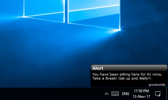
- Pop up Alert on Windows: This is the Growly notification. You can go inside and edit the message to be displayed accordingly. Mine gives a time of how long I have been sitting and tells me to take a break as pop-up notification on my desktop.
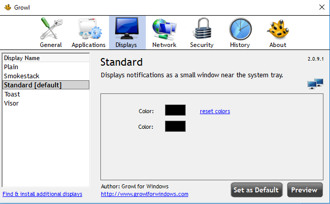
Now Run Growl program on your PC. Open Growl’s control panel for editing its settings. You can add notification alert sounds. Change the color and style of notification from the Display settings on the Growl Application. You can select the option to Run Growl at Windows Startup so that you don’t have to run it each time you open the PC.
Once that’s done, Deploy the code in Node Red and everything should work fine.
Create a batch file(Extension .bat) with the following content and save it with a .bat extension.
ECHO ON
ECHO Starting Node Red. Please Wait…
node-red
Add this batch file to the Windows startup folder (C:\Users\*YourUserName*\AppData\Roaming\Microsoft\Windows\Start Menu\Programs\Startup\). This batch file will run Node Red Server on Windows startup so that you don’t physically need to start it every time.
That’s it. Congratulations! You have made your Chair “Smart” 😀
Summarizing
- Buy a Force Sensitive Resistor from an online shop. Bigger the better.
- Find the pulldown resistance by the methods mentioned earlier.
- Get a Bolt WiFi Module and register it to the cloud. (You needn’t use Bolt, you can use any IoT platform but then steps won’t be similar as listed above)
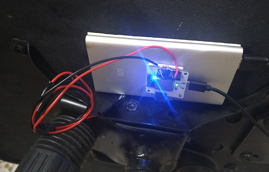
- Connect everything together and attach it to the bottom of your chair. You can power your module by a 5V power bank and keep it stuck underneath the chair.
- Install Node Red, its packages and run the Node Red Server.
- Copy the code mentioned above and import it into your Node Red Console. Edit parameters as necessary.
- Run Growl.
- Hit Deploy.
- Add the Node Red Batch File and Growl to your Windows Startup so that you dont have to do anything to set it up or run from the next bootup of your OS
- Sit back and relax. Let the smart chair tell you when to take break or to move around.
Here is how mine looked like in the end.
So I used Bolt’s IoT solutions for this product, here are my takeaways from the product.
What I liked
- Setup and getting started process was fairly easy and straightforward.
- Cost. At $12 in total, you get the hardware as well as lifetime access to their cloud services without any usage limits. For me, if they can deliver free lifetime cloud and API services for all their devices, it’s an exceptional deal. (But I don’t know how they can sustain as a company with that lifetime free claim. Maybe by cross subsidizing the maker community from their enterprise solutions? But hey, not my problem.)Post Edit: Bolt team told me now that they would probably limit usage limits on a daily basis for users. The exact free number of API calls/day or rates are not decided as of now. That’s a bummer. Team has confirmed that they are cross subsidizing.
- They are supposedly giving support to built-in Machine Learning algorithms on the platform which I haven’t seen many IoT platforms do. (Although I haven’t tried out this feature yet. They have Machine Learning Tutorial project there in the documentation)
- It has a great feature to deploy to multiple devices at once. In an enterprise scenario, where people might be dealing with 100’s of devices, device management would be very easy.
What I didn’t like
- In Hardware, I would have really loved it if they opened up their hardware firmware, so that I as a hardware tinkerer, can play around with the code(I currently can’t edit firmware in the device) to change settings, go into low power mode etc. I think the probable reason might be that they would have wanted people to use their hardware and not any random ESP8266 module which people might buy from somewhere else and use Bolt’s cloud services for free. Well, if that’s the case, I think they can fix it by giving cloud access as a one time paid service and limiting user accounts only when you purchase something directly from Bolt website.
Post Edit: I did talk to Bolt team about this, they said they are looking into a potential solution for this in the future, by releasing the firmware. But it’s not confirmed as of now.
- In documentation part, although I liked the quick-start guide. I do think they need to put out more detailed project guides for getting started with APIs and web side of things. Frankly, that’s where I spend most of my time over the weekend. I somehow do think, their documentation was skewed towards a software developer tinkering with hardware not a hardware developer tinkering with the software side of things.
- I would have loved to have a couple of changes to the hardware, like adding cut-able traces for bypassing the on-board regulator for low power stuff and maybe add pads for a coin cell holder(un-populated).
- One more crib would be(which would be a question to all IoT providers, not specific to Bolt), what would happen if Bolt IoT decides to shutdown one day? What happens to all the data and APIs? How will it affect me if I have 100 of these devices deployed on the field. That I guess is an issue with any startup IoT provider, I guess.
Post Script:
This has a been a fun little project. I had a good time with the Bolt Platform. It has its quirks but I am sure the team is working on it to fix most things. Regarding the project, I am sure I could do a much better job integrating this to a smaller form factor, probably with a coin cell battery and timer to sleep and conserve power and make this run for a long time beneath my chair. But that was kind of beyond the scope of this project.
If there is some interest in the community for this project, I might look to clean up this project in the future and see what all improvements can be made. On a tight schedule of about a day, I think I was able to put together something half decent. 😀
Hope you guys liked it and I hope you will try building one for yourselves soon if you are a lazy workaholic like me 😀
If you enjoyed this post you may like to check out my other posts too…
Hacking Indian Electronic Voting Machines
Christmas LED Lights Teardown
How to electronically track your Currency Notes
0 Comments
Comments are closed.