This is a follow-up post to a previously popular post of mine. Quite a few people build it successfully. I wanted to do a follow-up post to explain a few things which were missing on the post(Also correcting a small output tapping mistake which one of my readers who built it, pointed out). I wanted to extend the previous build to make a positive and negative ioniser. Build files are open-sourced and can be found here.
The previous build of mine creates a high voltage positive output with respect to the input. Now if you flip the diodes in the circuit, you should get a high voltage DC negative voltage at the output. Schematics are shown below for both of them. (Click on the images for a higher resolution view)
In the Github repo, I have also added LTspice simulation files with similarly rated parts so that you check the circuit functionality. Instructions for running the file can be found in the LTspice Simulation folder in the Github. For a 15 stage doubler, the output voltage will theoretically be around 6900V(230*2*15) for a 230V AC input supply.
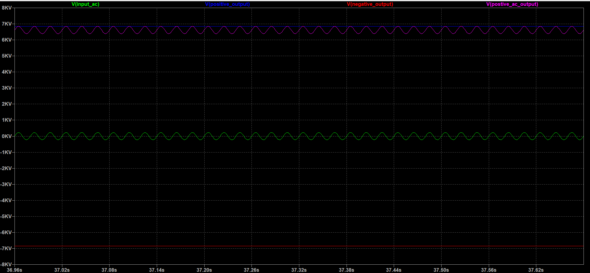
In my previous version of the build, I had connected the output at capacitor C29 which was a mistake while doing the schematic. This was spotted by one of the guys who replicated the build of the unit. Thanks, Karl for spotting the error. ? If you take the output at capacitor C29(Instead of capacitor C30) you will see a high voltage AC waveform, the last rectification(rather peak detection) won’t happen to smoothen the AC signal to the DC voltage. The circuit will still work with the old design but it won’t be a smooth DC at the output. I have made the corrections in the schematic and the layout.
Which one should you build?
Between the positive and negative output Ioniser, which one should you build? It’s up to you and it doesn’t really matter. I have built both and tried the smoke-in-the-jar experiments. Both cleared the smoke particles instantly. There wasn’t any noticeable difference.
Usually, Negative output ioniser is the one you would see commonly implemented in products. In some products, you will also find a high voltage positive ioniser attached outside the device in a mesh or flat plate so that the dust settles in that specific region. The particles will get attracted to the positive plate and will help reduce the mess.
The GitHub repo contains Gerber files and Eagle files for both designs. Just upload the Gerbers.zip files to any online PCB vendor for manufacturing it. You can get one set of Gerbers made and make the complimentary(Positive or Negative) ioniser by just swapping the diodes(By ignoring the diode orientations in PCB silkscreen). The bill of materials remains the same for both sets.
If you build a positive and a negative ioniser and bring the output needles close by you can see some awesome corona discharge.
Again please be very careful when dealing with high voltage outputs and the AC inputs. Please do go over all the safety tips mentioned towards the end in the previous post.
Do let me know how the build turned out. Build pictures, comments and critiques are always welcome.
If you enjoyed this post you may want to check out my other posts too…
From an Idea to Hardware Product Cycle
Build an Ioniser in under $10 – Part 1
Disinfecting CoronaVirus with Technology
A Smart Chair: For those Lazy Workaholics
Hacking Indian Electronic Voting Machines
Christmas LED Lights Teardown
How to electronically track your Currency Notes
Other Archives
0 Comments
Comments are closed.