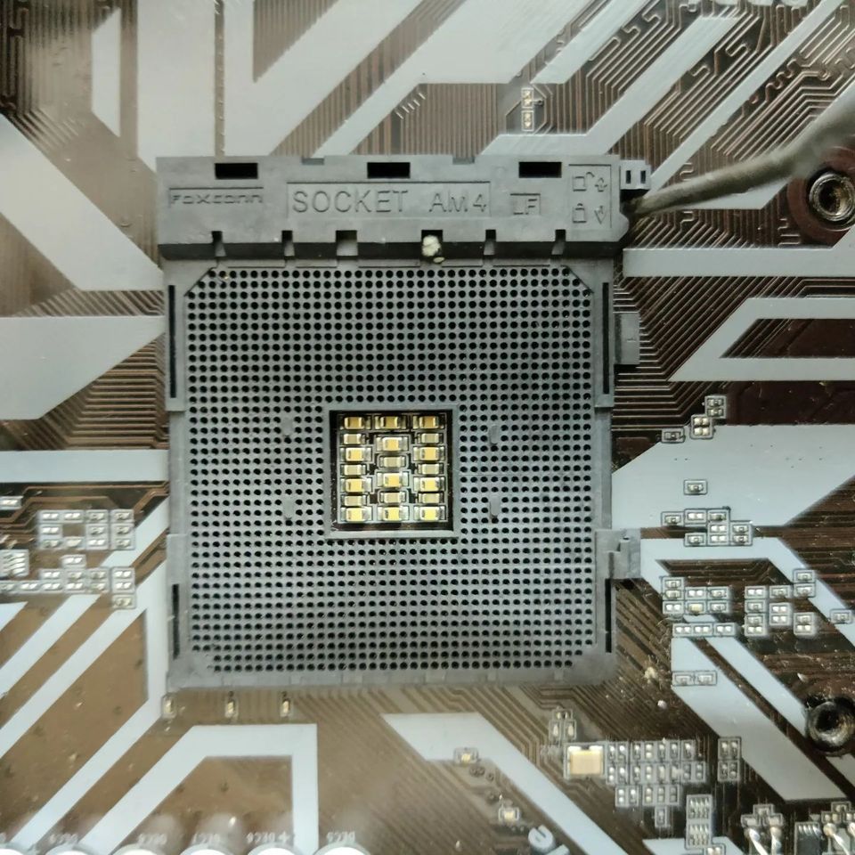
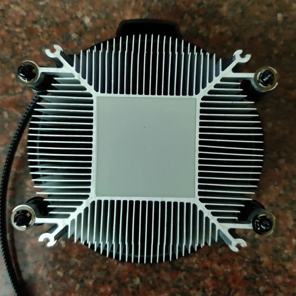
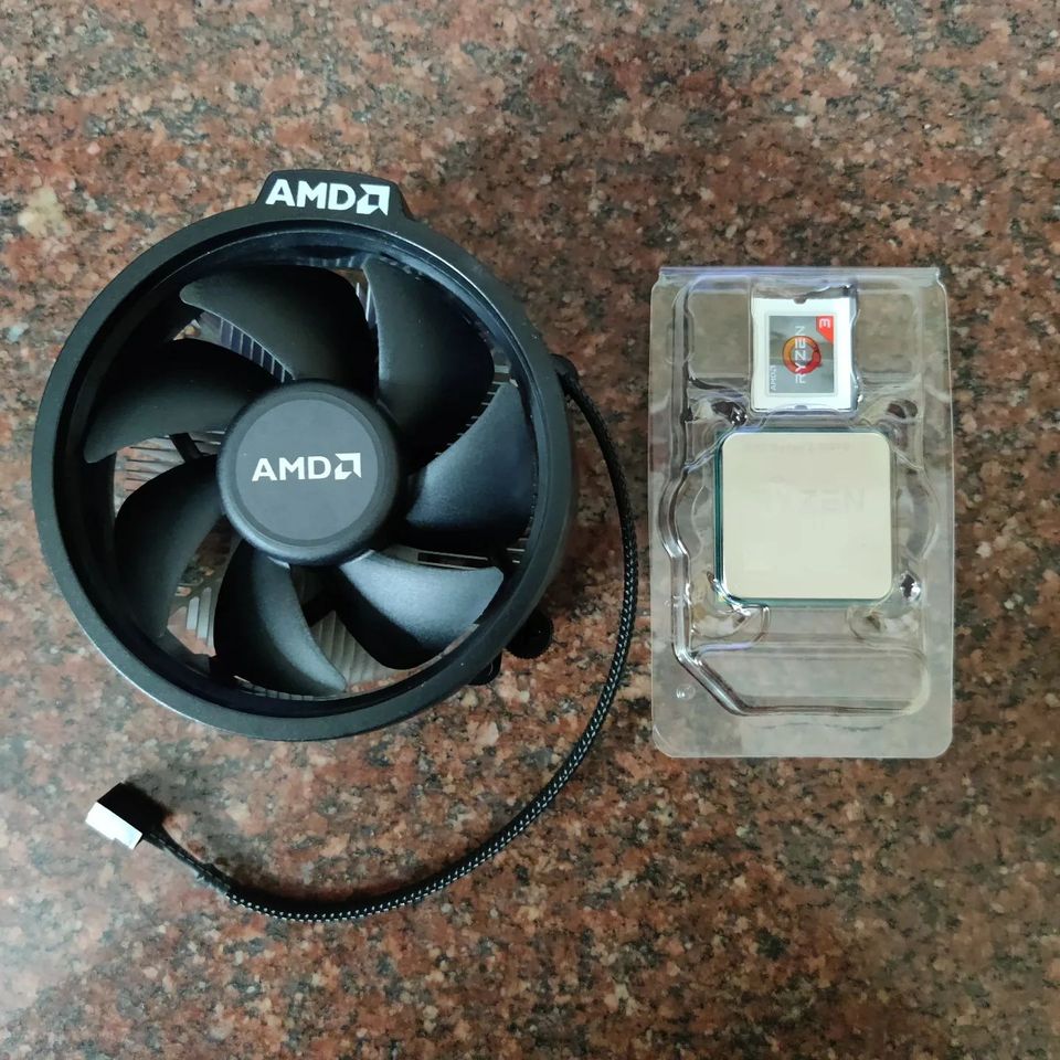
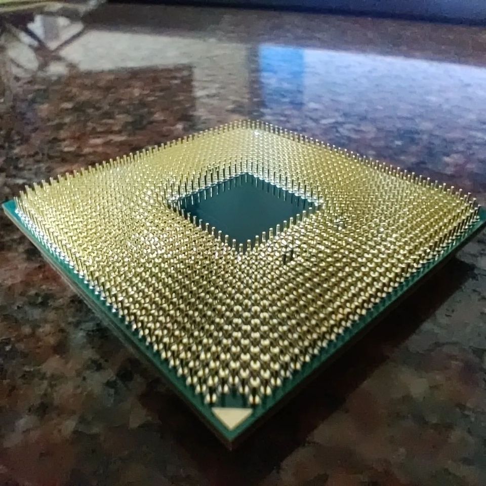
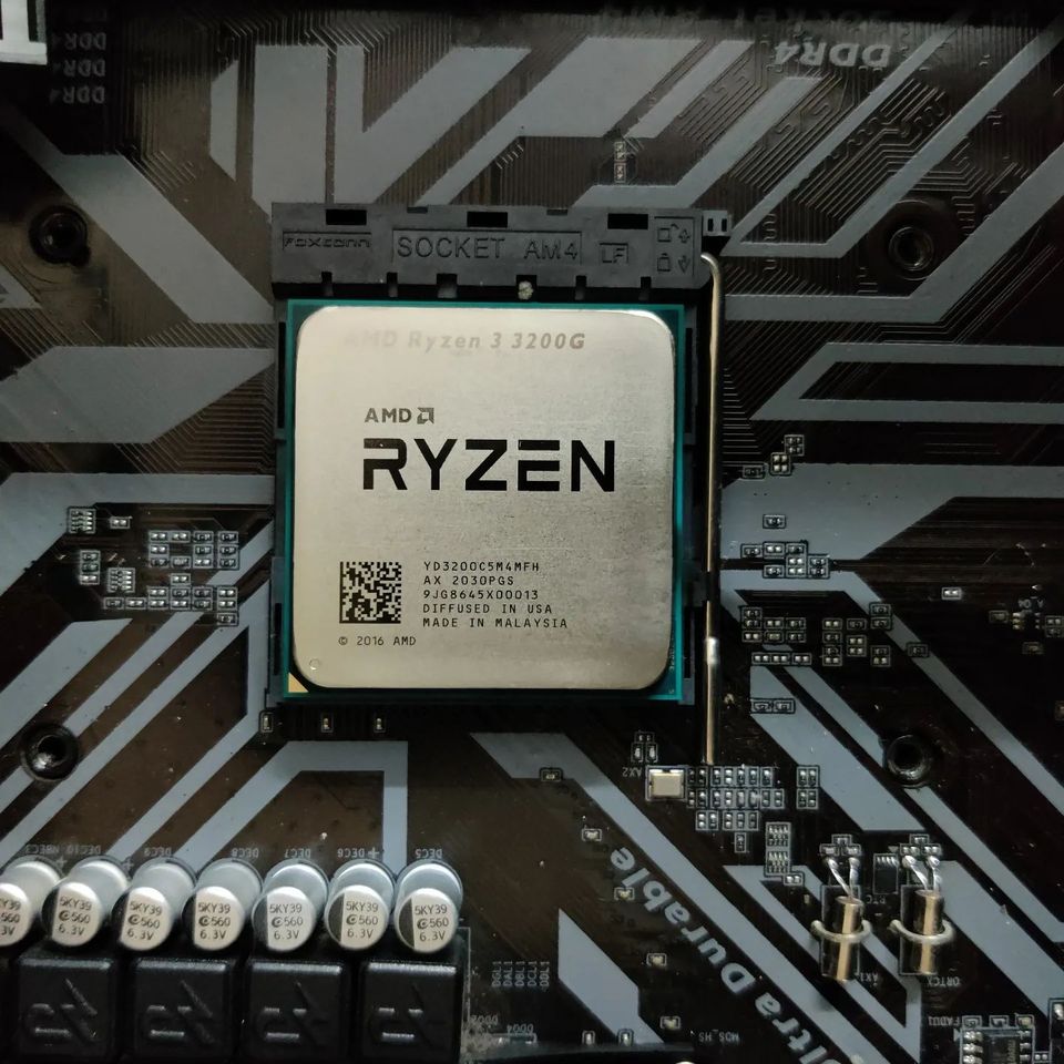
CoreMark: Benchmarking Processors

Developed by a non-profit, Embedded Microprocessor Benchmark Consortium(EEMBC) in 1997 is currently one of the most popular benchmarking software available to characterize and compare the processing capabilities of your embedded microcontrollers. It’s a piece of code that runs on practically any processor/controller out there and does a bunch of tests and reports the result in a standard format. The code conducts a bunch of integer arithmetic calculations, matrix manipulations, linked lists and state machine operations. So it does a few of the performance benchmarks which are used in real life (but it’s still synthetic testing though). CoreMark when it was released, was an alternative to another standard known as Dhrystone that was created back in the 1980s. The issue with Dhrystone was that you can always tweak certain settings to get a higher rating based on compiler optimisations.

CoreMark prevents compiler hacks and smart programming tricks to drive up the ratings. The tests and code are available for free on GitHub if you want to run them on any controller of your choice.

Why does this matter for an embedded developer? When you are searching for a new microcontroller for a project you can always look at the CoreMark numbers and make an informed decision(Usually the higher the better). Most good chip manufacturers give the CoreMark ratings on their products but each might give it in a slightly different manner. There are 3 key numbers you need to keep in mind for that. A single CoreMark number shows the overall performance of the chip. Then there is CoreMark/MHz which normalises the core performance based on the clock speed. A chip having a lower CoreMark/MHz can have an overall better compute capability if it’s run at a higher clock speed. The third is CoreMark/mA which gives you a flavour of energy efficiency/power consumption of your processor. So keep all of these in mind when comparing microcontrollers.

CoreMark scores submitted by users all around can be found at https://www.eembc.org/coremark/scores.php.

If you liked the post, Share it with your friends!

Back to Basics: PTC Fuses

PTC Fuses

Resettable fuses are one of the commonly used components in an electrical design. If you have never used them, consider starting to use them if your device will be connecting to an external power source. In case of an accidental short, it’s a live saver for your circuits. These are components that will sacrifice themselves temporarily(Reusable) to protect circuits that follow them. There are a few things to consider when you are selecting fuses in your design and its important for any new designer to know what they are

Trip Current: Minimum current needed to “trip” or stop the current flow at around 25C. This is the minimum current needed to activate your fuse, so make sure that your circuit current draw is less than this. This is the upper threshold and is dependent on temperature. Check the datasheet for graphs. Usually, this value will drop for larger ambient temperatures.

PTC Fuse
PTC Fuses

Hold Current: It’s the maximum current that the fuse can allow to go through it over a long time at around 25C. This number (or lower) should be what you should be designing your circuit input current for.

Trip Time: It’s the time taken by the fuse to activate when the trip current starts to flow. Lower the better.

Rated Voltage: Operating voltage of the fuse. Make sure your circuit voltages are below this number.

Always remember that PTC fuses are resistive based, meaning there will always be some I^2R power losses on the fuse during its normal use. There will be a voltage drop too as it’s connected in series. So try to select the fuses with lower resistance and always account for this voltage drop so that it doesn’t affect the circuit downstream. A classic example of this mistake might be that you are powering high power LEDs with constant voltage power input.

If you liked the post, Share it with your friends!
1 68 69 70 71 72 86