CES last month had LG and Samsung showing off their latest Transparent TVs to the world. Despite being in the limelight for a few years, the underlying mechanics never cease to amaze. How do these TVs achieve transparency? Where are all the wires?
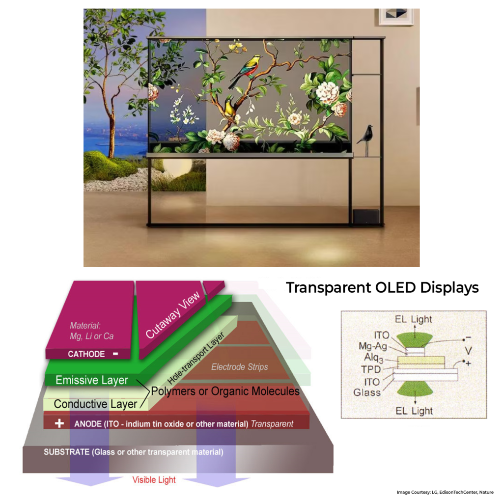
LG relies on Organic LED (OLED) tech for its transparent displays. OLED displays have organic layers responsible for light emission between two transparent electrodes. Electrodes made of metals are usually opaque. Enter the star of the show: Indium Tin Oxide (ITO), a transparent Conductive Oxide. What makes something opaque is the fact that the incoming light is reflected or absorbed completely. The light we see has photon energies between 1.6 & 3.2eV. ITO has a large bandgap of more than 3.5eV, which means it just allows light to pass through. With high Tin doping in Indium Oxide, it becomes conductive with low resistivity, making ITO an ideal choice for electrodes balancing optical transparency and electrical conductivity.

Constructing the display involves taking glass as a substrate, depositing a layer of ITO, and adding multiple organic materials (hydrocarbon-based) on top. These organic layers emit light when an electric current passes through them. The structure is completed with another electrode made of an ultra-thin Magnesium and Silver layer, achieving an impressive 70% transparency. To preserve organic layers from water/oxygen, they are sealed with an encapsulant.
Now we need transparent display drivers below them. For that, we use Thin Film Transistors (TFT) made of a material called Transparent Amorphous Oxide Semiconductors (TAOS). Deposited on a glass substrate (not silicon), all layers of a transparent TFT consist of transparent oxides. These transistors regulate brightness beneath each pixel by turning ON and OFF. Optical filters for RGB on each sub-pixel complete the one full pixel. Multiply this process over a rectangular space, and voila, you have a Transparent TV.
PS: Hopefully, this hasn’t offended any material engg. aficionados. I might have made a few broad statements. ????
