Back to Basics: AMR sensors

Today, let’s discuss AMR sensors. These sensors are still relatively new to many embedded builders because you mostly find them in motors, steering systems, actuators and industrial encoders. I thought it is worth covering for newer folks.

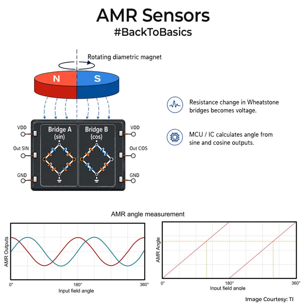
AMR means Anisotropic Magneto-Resistance. A thin magnetic film changes its resistance based on the direction of the magnetic field around it. So an AMR angle sensor is mostly asking which way the field is pointing, rather than only asking how strong the magnet is. Inside the chip, that resistance change is arranged as Wheatstone bridges. Think of them as tiny resistor networks that turn a small resistance shift into a voltage. With a rotating diametric magnet above the sensor, the outputs become sine and cosine signals. The MCU or the chip itself then calculates angle from those signals.

A basic AMR angle sensor repeats every 180°. It cannot naturally tell whether the magnet is at 30° or 210°. For full 360°, modern ICs they add Hall effect information. TI’s TMAG6180-Q1 mixes AMR with Hall quadrant outputs. Analog Devices’ ADMT4000 combines AMR with GMR(Giant magnetoresistance) for 360° and multiturn tracking.

Accuracy is where AMR becomes useful. Some have around 0.25°-0.5° angular error. These results depends on magnet centering, air gap, temperature, ADC quality and calibration though so expect that result always.

You will see AMR as angle sensors, linear position sensors and magnetic switches. Its usually used for motor rotor position, robotic joints, valves, e-bike motors, steering angle and compact encoders. AMR sensors can offer very good signal-to-noise performance and fast response times, making them attractive for high-speed control loops and precision motion systems where reliability and repeatability matter.

AMR sensors definitely have their place, especially when accurate angular position sensing is required. Just don’t confuse them with Hall effect sensors. While both use magnets, they operate on different physical principles and are often chosen for different design goals. We’ll dive deeper into that in future if needed.

If you liked the post, Share it with your friends!

Back to Basics: High-side and Low-side MOSFET Switches – Part 2

Last week we discussed high-side and low-side switching in detail. Today I wanted to extend that with three simple MOSFET cases that you will see again and again in real circuits. I have attached circuit diagrams so you can follow along.
Before that, a quick MOSFET refresher, in case you have forgotten,
For an N-channel MOSFET: Positive Vgs turns it on, Near-zero Vgs turns it off
For a P-channel MOSFET: Negative Vgs turns it on, Near-zero Vgs turns it off

Case one is the classic NMOS low-side switch. The load sits between VDD and the drain, the source goes to ground, and the gate is driven by your MCU(Lets say, 3.3V). When the gate goes high, Vgs becomes positive, the NMOS turns on, and current flows through the load to ground. This is why low-side NMOS switching is the default choice for LEDs, relays, buzzers, and many small loads. The small resistor from gate to ground is there so the gate does not float at reset.

Case two is a PMOS high-side switch when your MCU voltage and VDD are the same, like 3.3V. Here the PMOS source sits at VDD(Not like the NMOS). Pull the gate down to 0V with the MCU and the PMOS turns on. Drive the gate back up to 3.3V and it turns off. This is the simplest way to switch the positive rail when you want the load to keep a solid ground reference.

Case three is the one that trips people up. If VDD is higher than your MCU voltage, a PMOS cannot usually be driven directly from the MCU. A 3.3 V output is still lower than a 5V, 9V, or 12V source, so the PMOS may never fully turn off. That is why you add a small NMOS stage. 3.3V from the MCU turns NMOS on, so NMOS pulls PMOS’s gate to 0V and the PMOS turns on. When MCU low turns NMOS off, and R7 pulls PMOS’s gate up to VDD, turning the PMOS off.

Hope these circuits help as a refresher. One practical reminder though. In the LED examples, the series resistor sets current. If you swap the LED for a relay or coil, that resistor is replaced by the load, and you must add a flyback diode across it.

If you liked the post, Share it with your friends!
1 2 3 74