Recently, while discussing a project with a client’s junior team member, this topic came up. I thought it is worth explaining from first principles for folks starting out.
At the simplest level, both are just ways of using a MOSFET as an electronic switch to turn a load on and off. That load could be an LED, relay, solenoid, motor, or a small module. The difference is where you place the MOSFET in the current path.
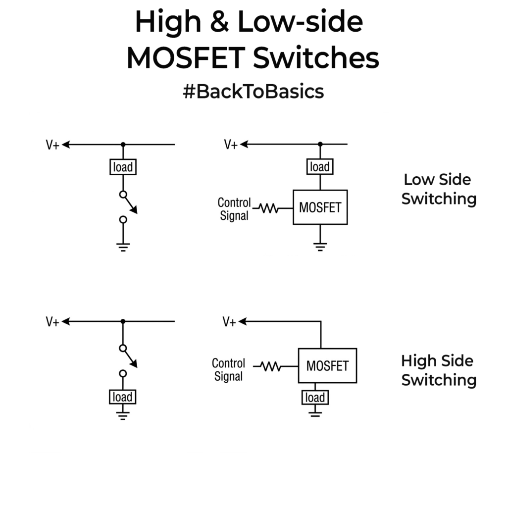
In a low-side switch, the MOSFET sits between the load and ground, so it switches the return path. In a high-side switch, the MOSFET sits between the supply and the load, so it switches the positive rail. That’s why the naming is like that. You are switching the low side of the load or the high side of the load.
Low-side switching is usually the first thing you will see in practical designs because it is easier to drive, especially with an N-channel MOSFET. Your controller is already ground-referenced, so the gate drive is simple. That is why it is so common for relays, LED strips, buzzers etc.
The tradeoff is that when you switch the low side, the load is not firmly tied to ground when it is off. It can float. For simple loads this is often not a problem. For sensor boards, communication modules, or anything connected to other powered signals, that floating node can cause problems and hard-to-trace leakage paths.
High-side switching is popular when you want the load to stay referenced to ground, and you want to cut the supply instead. That often makes the overall system behave more cleanly. The con is that the drive method is usually more complicated. A PMOS can make high-side switching easier, but it is often less efficient than a similar NMOS. A high-side NMOS is better electrically, but usually needs a proper driver.
If there is interest, I can do a part 2 next week with actual circuits, drive options with NMOS and PMOS and explaining how it works + common issues to watch out for. Let me know via comments if that would be useful.