I was doing some research for a client project this week. The solution eventually needed some eddy current displacement sensors. It’s the kind of tool you forget until contact measurement starts to become a problem. Let’s discuss that this week.
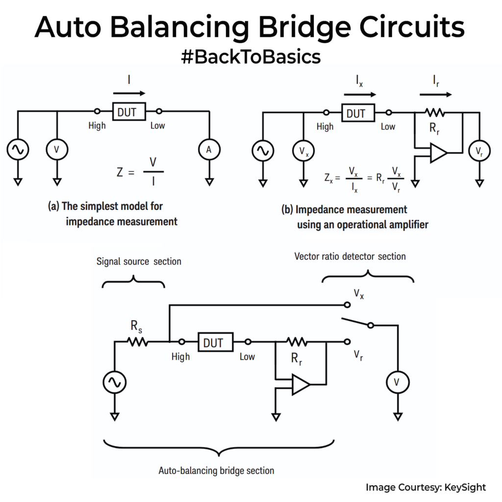
An eddy current displacement sensor is basically a coil driven with a high-frequency AC signal. That alternating field induces circulating eddy currents in any nearby conductive metal. By Lenz’s law, the magnetic field produced by those eddy currents opposes the probe’s field. For the same drive current, the probe coil stores less magnetic energy because some of the field is being pushed back. From the coil’s point of view that shows up as a drop in effective inductance, so the inductive reactance term falls. At the same time, energy is dissipated as I²R heating in the target, which the coil feels as added loss, so the effective resistance rises.
The probe electronics drive the coil at a fixed frequency and measure the resulting voltage/current amplitude and phase, infer the complex impedance (R+jωL), and then use a stored calibration curve to convert that impedance change into a distance output.
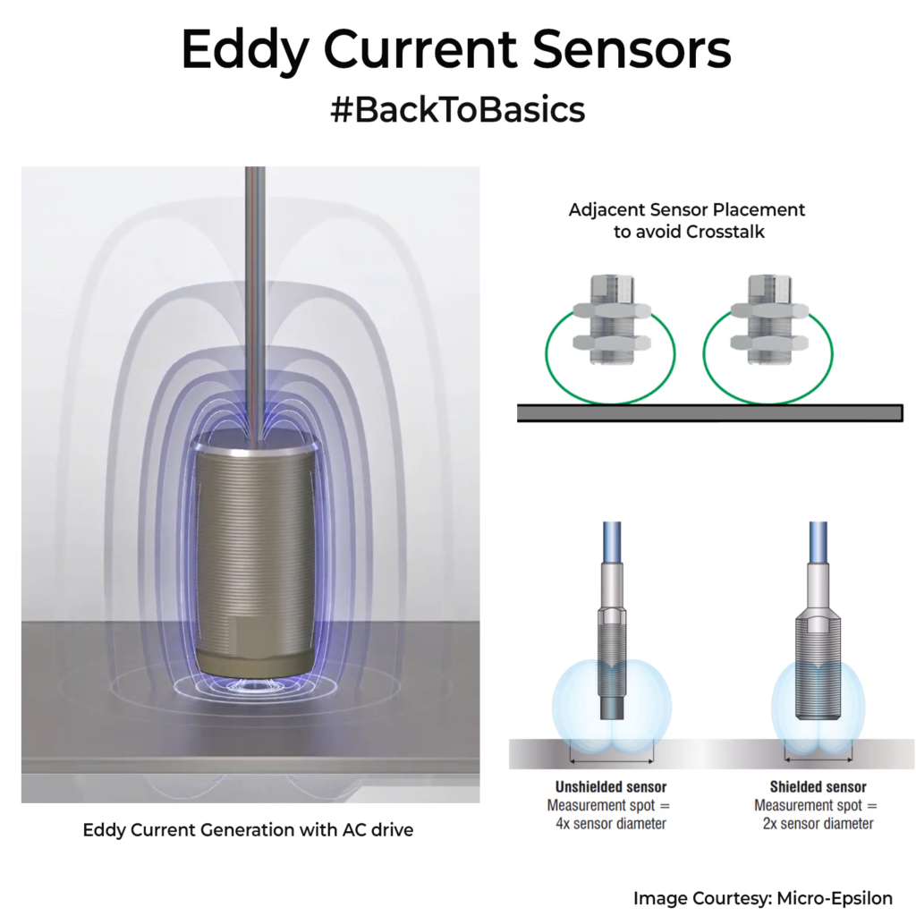
These sensors are used when you need reliable distance or vibration data in harsh conditions. Like maintaining tip clearance, predictive maintenance on rotating equipment cases, measuring shaft runout etc. They’re popular because they’re non-contact, fast, and can work in all the worse places with oil mist, dust, coolant spray, and even high-temperature scenarios.
The biggest tradeoff is that they only see conductive targets, range is usually a few mm (to low cm), and readings shift with material, geometry, EMI pickup, and temperature, so mounting, shielding, and calibration matter in real machines. Most companies providing the sensors, also do give the matching drivers with temperature calibration as a full set.
If you plan on using multiple of these units, please space them out so that one sensor’s field doesn’t affect the field of the other. Some systems use different drive frequencies for adjacent units.