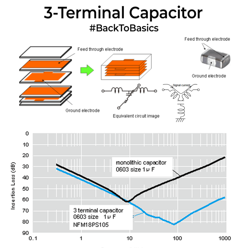
Since last week’s post got many of you interested in 3 terminal capacitors, I thought we should discuss a bit more on this. Quick reminder: In a 3 terminal capacitor your power rail/signal enters one end, exits the other, and the ground electrode sits in the middle. Many parts look like 4 pads because the ground is split into two pads that are the same node.
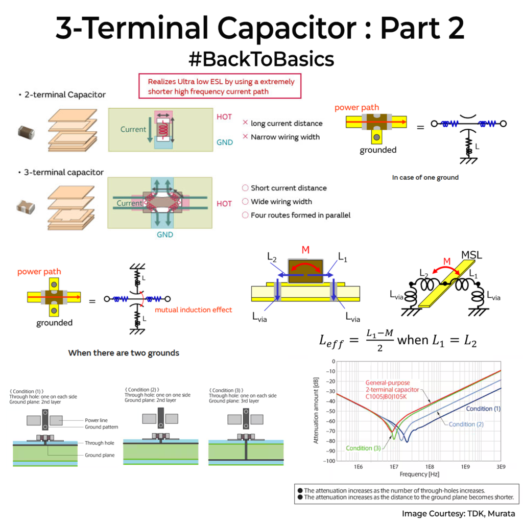
So, how to place them in circuits? There have been a lot of combinations that have studied on how to use the GND vias. Check images. Those two ground pads are not optional. If you connect only one side to ground, you bring back the same loop problem you were trying to fix. When you stitch both sides into a solid ground plane, the return paths are shorter, the loop area is smaller, and the magnetic fields partially cancel. ESL is reduced due to mutual induction effects when current flows from the centre of the component to the left and right sides. You will see suppression values much lower in this case.
Your PCB stackup also matters in these things. You need to have the GND plane as close to the signal layer possible because the via is shorter and inductance is smaller. The number of ground vias matters too. App notes show that two vias, one on each side of the ground pattern, gives better attenuation than a single via, and shallow vias beat deep vias at the same count. Via-in-pad can help if your fab allows it. A ground via placed in the middle of the split ground pads will reduce ESL too.
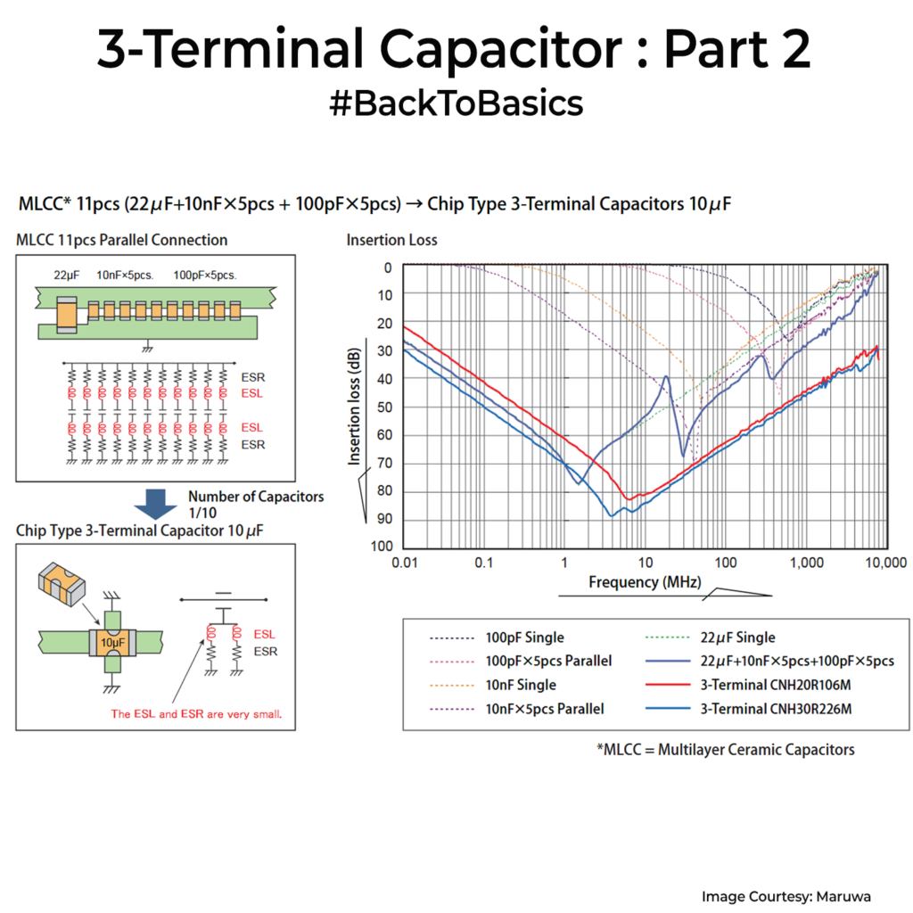
This is also why these parts can reduce component count. If your fix today is using three or four 0.1µF caps scattered around a boundary, a single well grounded 3 terminal part placed at the boundary can often replace the whole cluster and behave more predictably at high frequency.
Murata and TDK have great app notes with mounting drawings and measured curves, and they are worth going through before you commit to a footprint. I really do think for high speed designs, you should start considering them if you are not already using it.