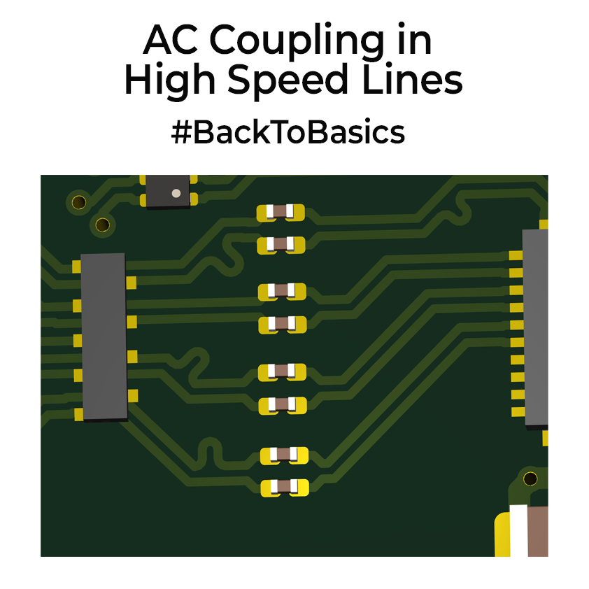
I was doing some high speed PCB designing and thought AC coupling capacitors that are placed on high speed differential lines might be a good topic to discuss today. These are series capacitors you will see placed in USB 3/4 lines, PCI Express, HDMI etc.
Like any capacitor, at DC, it’s an open switch, at high frequency, it’s a dead short. Why do you need it? It blocks any DC voltage. Every differential link has two voltages: the desired differential swing (like +/-400mV) and an unwanted but expected common-mode voltage that both wires sit on, measured with respect to ground. The series capacitors block the DC part, letting each side of receiver/transmitter to coexist without any issues.

If there is any small ground offset(in mVs) between two sides, it would push a continuous long term DC current and waste power. Coupling caps block them. It also allows for hot plugging. Meaning if one side is powered, the other side is off, without any series capacitors, live driver will push DC current straight into pins that are still at 0 V, which is bad. By inserting series caps, you ensure no DC flows until both ends are fully powered and switching.
How to choose one? Most specs put cap values between 75nF and 220nF. With the 100Ω termination, that puts the high-pass freq in the tens of kilohertz, well under the spec to pass gigabits of data. I usually prefer using 0201 type capacitors, purely because they are small(low inductance) and they fit the differential pair lines width without majorly spacing it out. Placement matters. I place one cap in each leg, side by side, same orientation, pads inline, so the pair runs straight through. Keep stubs under half a millimetre and return to 100 Ω within a millimetre. Most spec/chips will tell you what you need to do.
Please take care of them while routing. They look tiny but if you get their placement or value wrong and your gigabit link will fail. It’s hard to debug them unless you have some high-end oscilloscopes. So treat them well.
0 Comments
Comments are closed.