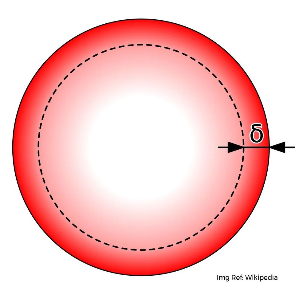
Skin effect is a phenomenon that occurs in conductors carrying alternating current (AC), in which the current density is highest near the surface of the conductor and decreases towards the centre. It’s measured as the distance from the outer surface of a conductor to the point where the current falls to 37%(1/e) of the max current value. It depends on the frequency of the signal travelling in the cable. Higher the frequency, lower the depth from the surface it travels. For a DC signal(f=0Hz), it travels through the entire cross-section of the signal.
So Why does it occur? When an alternating current flows through a conductor, it generates a changing magnetic field around the conductor. This magnetic field, in turn, induces an opposing electric field within the conductor, which creates eddy currents that flow in a circular path around the conductor. These eddy currents produce a secondary magnetic field that opposes the original magnetic field. This field is strongest in the centre and hence it pushes the current towards the outer surface of the conductor.
This means that to carry a high-frequency signal, it’s relatively wasteful to have a very thick conductor as most of the current is on the outside surface. Hence you would see the usage of multi-stranded wires than solid core wires to carry these types of signals. Induction cooktops you use to cook food in your kitchen also rely on high-frequency switching coils. Due to its high freq, the skin depth kicks in and heating only happens in a thin region of the bottom surface of your pan. Skin depth depends inversely on the conductivity of the material and magnetic permeability. Better a conductor, lower the skin depth. Similarly, more magnetic a material, lower the skin depth. For PCB designs in very high frequencies, Skin depth usually would need to be factored in the field solver as impedance will get affected.
0 Comments
Comments are closed.