Back to Basics: Inductor Rated Current vs Saturation Current

Saturation Current

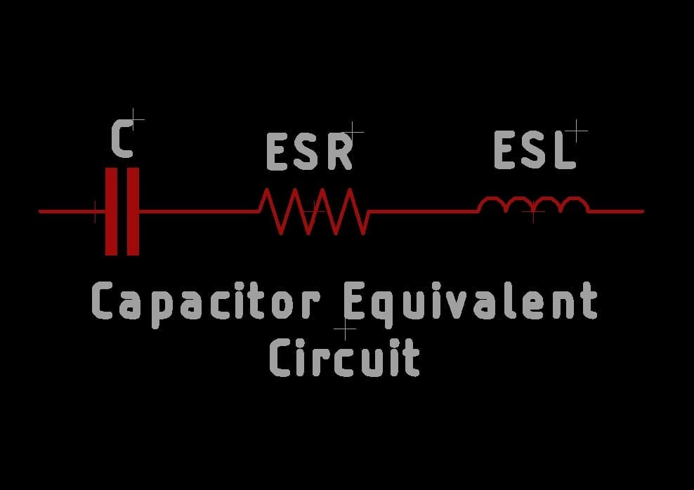
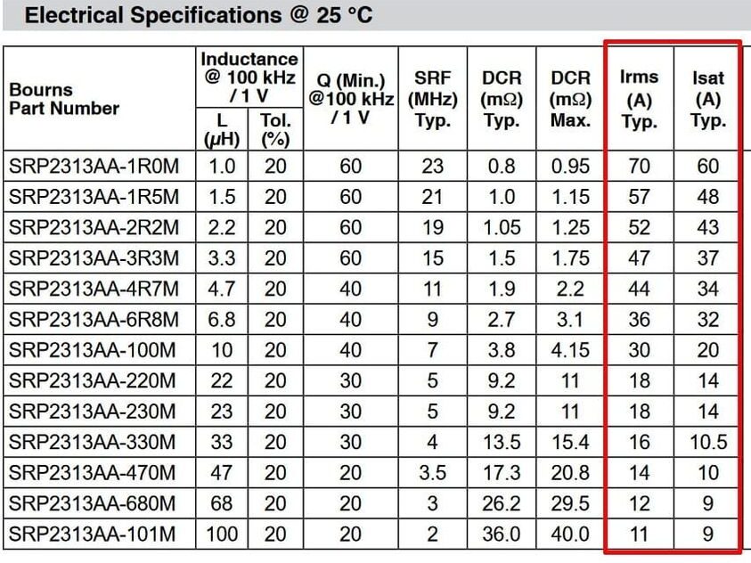
When choosing inductors in your design, one of the most confusing aspects is the rated current and saturation current values(there are other alias names like Irms, Itemp etc) mentioned in the datasheet. In older datasheets, these are rarely explained. What should you choose as the upper limit current rating for your inductors? Sometimes saturation currents are more than the rated current. It becomes a troublesome design choice till you understand what these actually are.

Rated current is the amount of current that can go through an inductor to heat it up by a fixed temperature value from the ambient(usually 40°C). Meaning if the rated current is 3.5A, once this amount of current is passed through the inductor and once a steady state is reached, the temperature of the inductor will be 65°C if the ambient temp is considered as 25°C.The saturation current mentioned in the datasheet is the current that when passed through the inductor, it becomes “saturated” and starts losing its inductance value by 20-30% of the original value.

So when choosing an inductor you can push the current values to maximum saturation current before inductor values start to drop(Ideally you shouldn’t but you can). You can pass more current than the rated value through an inductor, provided, you can give adequate cooling for your inductor. It’s given in a datasheet so that you don’t exceed the operating temp range of the inductor. If you are using the inductor in a use case where your ambient temp is 70°C, at rated current, the inductor temp will be 110°C which might be beyond the operating temp of the inductor packaging and it will stop working altogether.

So choose your inductors carefully. It’s not always about the inductance values alone.

If you liked the post, Share it with your friends!

Back to Basics: Equivalent Series Resistance (ESR)

Capacitor Equivalent Circuit

In real life a capacitor is not really a capacitor alone, it will have an internal resistor and an inductor. This resistance is what is known as an ESR. We ideally want ESRs to be tending to a low value as they are the primary cause of switching losses in a capacitor. These vary with the temperature and type of construction of the capacitors. Electrolytic caps usually have higher ESRs.

So why should you care about ESRs in your design process? Usually large electrolytic caps are used as bulk storage to maintain a voltage rail in the input of a system(To avoid voltage drops at high frequency). Now you have a high ESR capacitor, it won’t be able to deliver the charge to the system quickly because of the series losses in the ESR. That in turn will heat up the capacitor to potentially dry up the internal dielectric material as well. So in order to reduce the switching losses, try to use good quality capacitors with lower ESRs in your design if you have the budget for it. One trick is to use multiple caps of the same ESR, in parallel, to effectively reduce the ESR. High ESR caps reduce the longevity of your design with use.

ESRs are mentioned in the datasheets and is specified by measuring the resistance at a frequency of 100KHz. It’s done with an ESR meter which injects a 100KHz low voltage signal and measures the voltage across the capacitor to estimate the ESR(As at high freq, the capacitor will be having negligible impedance). This voltage is converted to resistance to give you the actual ESR of the capacitor being tested.

For circuit debug/repair work, ESR meters are a good tool to have because they can be used to measure ESR in-circuit(Without removing the part from PCB). If the ESR meter reads high(Usually bulgy electrolytic caps, but remember they need not be always bulgy), that’s a bad cap and you can remove that specific capacitor to replace it with a new one.

If you liked the post, Share it with your friends!
1 16 17 18 19 20 24