Back to Basics: Oscilloscope Part 9: Current Probes

Oscilloscope Current Probes

We can’t close this series on scopes till we discuss the current probes. For measuring current waveforms there are two main methods, one is adding a small resistor in series in the current path and measuring the voltage diff across the resistor with a differential probe as we discussed last week. This method is cumbersome and you can’t always cut up a cable/track to add the resistor.

Internals of a Clamp of a Current Probe

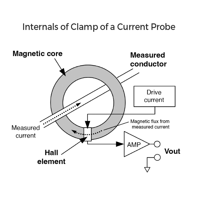
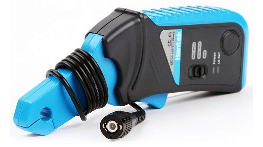
The other way is via Current Probes. A current probe consists of a magnetic core and/or a Hall effect sensor positioned within a clamp. Probe jaws are placed around the conductor you want to measure. Whenever there is a current flow, it induces a voltage in the magnetic core inside the probe. This voltage is directly proportional to the rate of change or derivative of the current enclosed by the loop formed by the probe jaws. To measure DC, you need a hall effect sensor on the core. Hence you see a split core design with it. The induced voltage is fed to an instrumentation amplifier/signal conditioner and fed to the input of the oscilloscope. The probes mention a voltage/Ampere rating with which you will be able to determine the current value on the scope. Select a probe with the appropriate sensitivity for your specific application to measure low signals accurately.

Personally, I use these clamps to measure coil currents in motors clamping around to fine-tune motor currents. It’s a lifesaver for me there.

Pro Tip: To increase sensitivity when measuring small currents, wrap multiple turns through the primary of a current probe.

Concluding the oscilloscope series! It’s been a journey. If you enjoy long post-series like this, drop a comment. Next week, we dive into a new topic!

If you liked the post, Share it with your friends!

Back to Basics: Equivalent Series Inductance(ESL)

For a real-world capacitor, there are 2 elements worth exploring, ESR(Check older posts to know more about this) and ESL. ESL refers to the inductance that is present in the leads and terminals of a capacitor, as well as any inductance that is present in the capacitor itself. As you see in the equivalent of a capacitor, it’s an RLC circuit, and RLC circuits have a self-resonant freq when the effective inductance and capacitance “cancel” each other and show a minimum impedance. You would have seen those in the V-shaped impedance curves for capacitors. The lowest point of the V shape is the resonant frequency.

After the resonant frequency, Capacitor doesn’t work like a capacitor. An ideal capacitor is supposed to have a lower impedance for larger frequencies of operation. Xc is inversely proportional to Freq. What we see after the resonant freq in the graph, is due to ESL. The inductance of a capacitor starts dominating and the impedance rises. Now, what’s the problem if impedance rises? Suppose you are using a capacitor beyond the resonant freq in your circuit, impedance seen by your power supply rails will be higher, meaning it will actually resist the flow of high freq components creating noise problems or spikes at the switching instant. Hence we always want to use capacitors with lower ESL in our circuits.

The amount of inductance in a capacitor is primarily influenced by the length of its constituent elements. As the length, or loop area, increases, so does the inductance. Consequently, electrolytic capacitors tend to exhibit significantly higher ESL than their 1206 or 0402 (which is even lower than 1206) counterparts. It is therefore advisable to use the smallest possible footprint size that is compatible with the required voltage rating, in order to minimize ESL. You see that on the graphs, the resonant point shits right and the vertical impedance axis value reduces as you go down in size. Another way to reduce it is to use a flipped capacitor(Check older posts on how they work) with a lesser length.

If you liked the post, Share it with your friends!
1 6 7 8 9 10 24