For the last two years, HyperX Cloud Alpha Wireless Headset has been my daily driver. I had even written earlier about its absurd 300hr battery life. One full charge would last me close to a month of daily use, meaning I have probably charged it only 25 to 30 times in total. Last week, a problem emerged.
This headset uses a soft power button, so you hold it for a few seconds and the system wakes up. Last week, pressing this button didn’t turn on the device. Initially, I thought it was a low battery issue and kept it on charge for about half an hour before trying to turn it on again. Still nothing. It was working perfectly fine the day before and there was no sign of any damage. To diagnose the root cause, I opened up both halves of the ear drivers and looked for usual failures like broken solder joints or loose battery leads. Everything looked fine. It still refused to turn on.

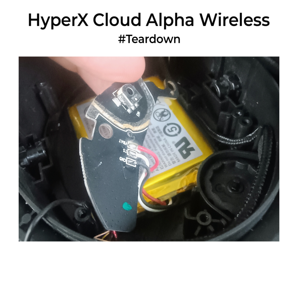
It seemed hung. That’s when it hit me. Its actually hung in some weird software state which prevents the button press from triggering. My guess was that the microcontroller had landed in some bad state. I can’t reset it because there is no physical battery cutoff button. With that in mind, I disconnected the battery by desoldering the ground line, then soldered it back. Instant recovery. The controller rebooted, and the headset came back online as if nothing had happened.
As a hardware designer, I think products with soft power control should always have a recovery path. A hidden reset switch, a battery disconnect or at least a watchdog timer in firmware would have prevented this. (Refer to older posts to learn more about watchdog timers). It is one of those small design choices that users never notice until it is missing.
I have updated the headset firmware since then, so maybe this bug is fixed now in software. Still, this felt more like an engineering oversight from the team.
BTW as I always say, DO NOT be scared to open up electronic things. Try to understand them before you replace them. A lot of dead gadgets are just one power-cycle away from working again.