Back to Basics: What does p in 1080p stand for?

Yesterday I was doing some research into display drivers for a project and got to learn about how the TV displays evolved. One of the things I learned was contrary to popular belief, it’s not pixels – it stands for “progressive.” Let me explain.

The “1080” part of 1080p stands for the number of pixels in the vertical direction of your display. It can be 720, 1440, 2160, etc. When you are trying to display something on a screen(called “scanning” the screen), there are 2 ways of doing it. Interlaced scan and Progressive scan. In an interlaced scan, the image to be displayed is divided into two fields, and only half of the lines are shown at a time. The first field includes the odd-numbered lines(1,3,5,..,1079), and the second field includes the even-numbered lines(2,4,6,…,1080). These fields are then displayed alternately to create a complete frame. Meaning, that at a single time, only half the screen is refreshed to a newer image. This was done in the olden days of CRT Displays to show higher-quality images on screen with only half the bandwidth. It reduced the transmission rate needed for videos. But this has drawbacks for fast-moving scenes, you may observe some stripes/artifacts in the screens for these videos.

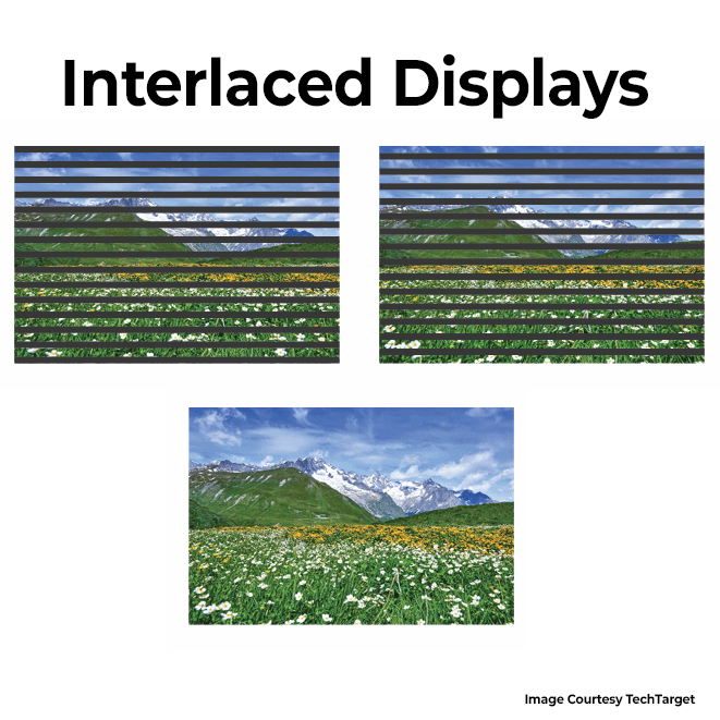
Now Progressive scans, on the other hand, displays or “scans” every 1080 lines one by one, top to bottom, and refreshes every pixel on the screen at the same time. That means full bandwidth is needed to show a frame. Progressive scan provides a smoother, faster, and more detailed image, making it a preferred choice for modern displays. You don’t find interlaced formats that much these days.

Now you know what “p” means. Who knew pixels could be so progressive? ????

If you liked the post, Share it with your friends!

Back to Basics: Freewheeling diode and How to choose one

I was designing for some motor applications earlier in the week and had to select a freewheeling diode for the circuit. So, I thought it might be a good time to cover that here. Freewheeling or Flyback or antiparallel (there are more aliases as people call it whatever they want) diodes are normal diodes used uniquely in a circuit. It’s connected right across an inductive load like a motor.

So how does it help? Take the example shown in the image, there is a motor that is turned ON/OFF with a MOSFET. During the ON cycle, the current flows through the inductor/coil of the motor, and the motor rotates. Now let’s turn OFF the MOSFET, the current flow from the power source suddenly stops. From Inductor 101, we know that an inductor doesn’t like abrupt changes in current and it has stored energy( in its coils(magnetic fields) during the ON cycle. Since the circuit is open, it has no way to discharge that energy, which means there will be a large spike in voltage at the inductor node, potentially damaging the MOSFET.

To avoid this, we place a diode in the opposite direction across the inductor which opens a new path for the energized inductor to discharge on its ON. In normal operation, since the diode is reverse-biased, it doesn’t affect the circuit.

How do you select one for your design? Choose a Schottky diode as it is faster to react. Find the maximum current passing through the motor/inductor during normal operation, your diode’s average forward should be much higher than this value. I personally use times x2 as a safety margin(if I am not penny-pinching on BOM prices). The maximum reverse voltage rating of the diode should be again higher by a factor of 2 compared to the normal working voltage applied across your motor. That’s basically it. You can select a freewheeling diode keeping these in mind and it will work just fine.

Hope that was helpful.

If you liked the post, Share it with your friends!
1 34 35 36 37 38 87