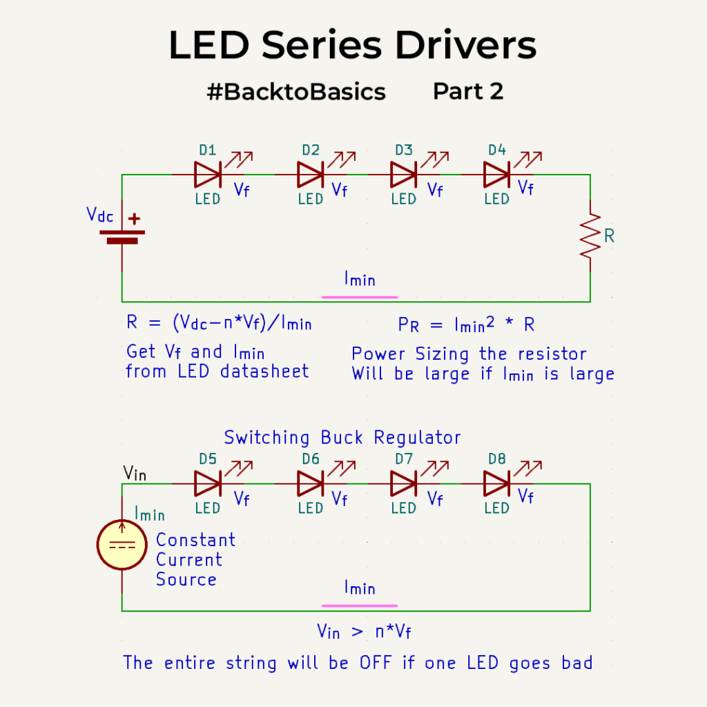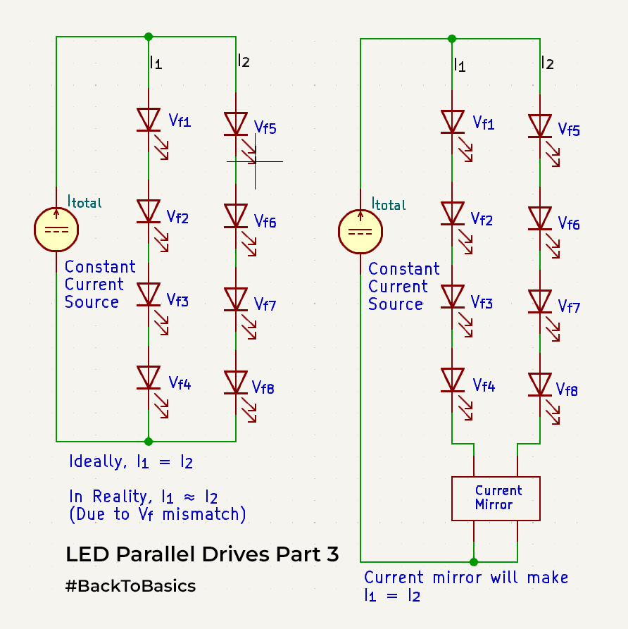
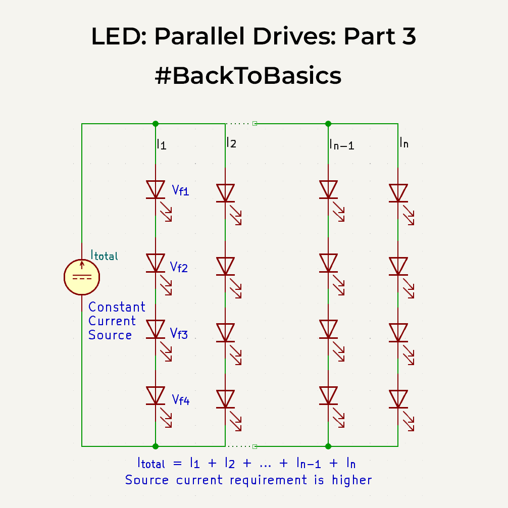
Last time we saw the pros and cons of driving LEDs in a series drive. An alternate approach is a parallel drive. As the name suggests, parallel drive involves sets of LEDs in series, interconnected across each other. Since you can have many parallel arms, the overall voltage required across a string is lower, hence even with a constant current or a buck regulator, you can drive a lot of LEDs. That’s the biggest advantage of a parallel drive. The source will ideally split currents across the different arms. Practically though, because of variations in Vf’s, each arm will have a slightly different forward voltage, which will cause a slight mismatch in currents through the arms which may cause some strings to glow brighter.

To fix this, you would need a current mirror circuit across each of the arms. For 2 parallel arm circuits a simple NPN current mirror will ensure that the current in one arm mirrors the other. If there are more than 2 arms, there are certain LED driver ICs that can control multiple arms and ensure that the current is the same in each of them. But they are expensive.
In parallel LED setups, if one arm’s LED fails as an open circuit, the whole arm goes out, and the constant current source diverts excess current to the remaining arms. If you’ve fine-tuned the LED drives to operate at peak current in each arm, a failure in one arm can lead to an increase in current through the others. This, in turn, heats up the LEDs, causing a drop in Vf and even more current flow. It sets off a chain reaction, ultimately leading to the failure of all arms over time.
So when driving in parallel mode always make sure the current in one arm is not driven at LED max current. Additionally, whenever possible, incorporate more parallel arms (as long as the input current source can handle it) for increased longevity. With more arms, even in the event of a failure in one arm, the rise in current in the others will be a relatively small factor, as there are more arms to share the current load.
We will cover one more variation of LED drives next time.