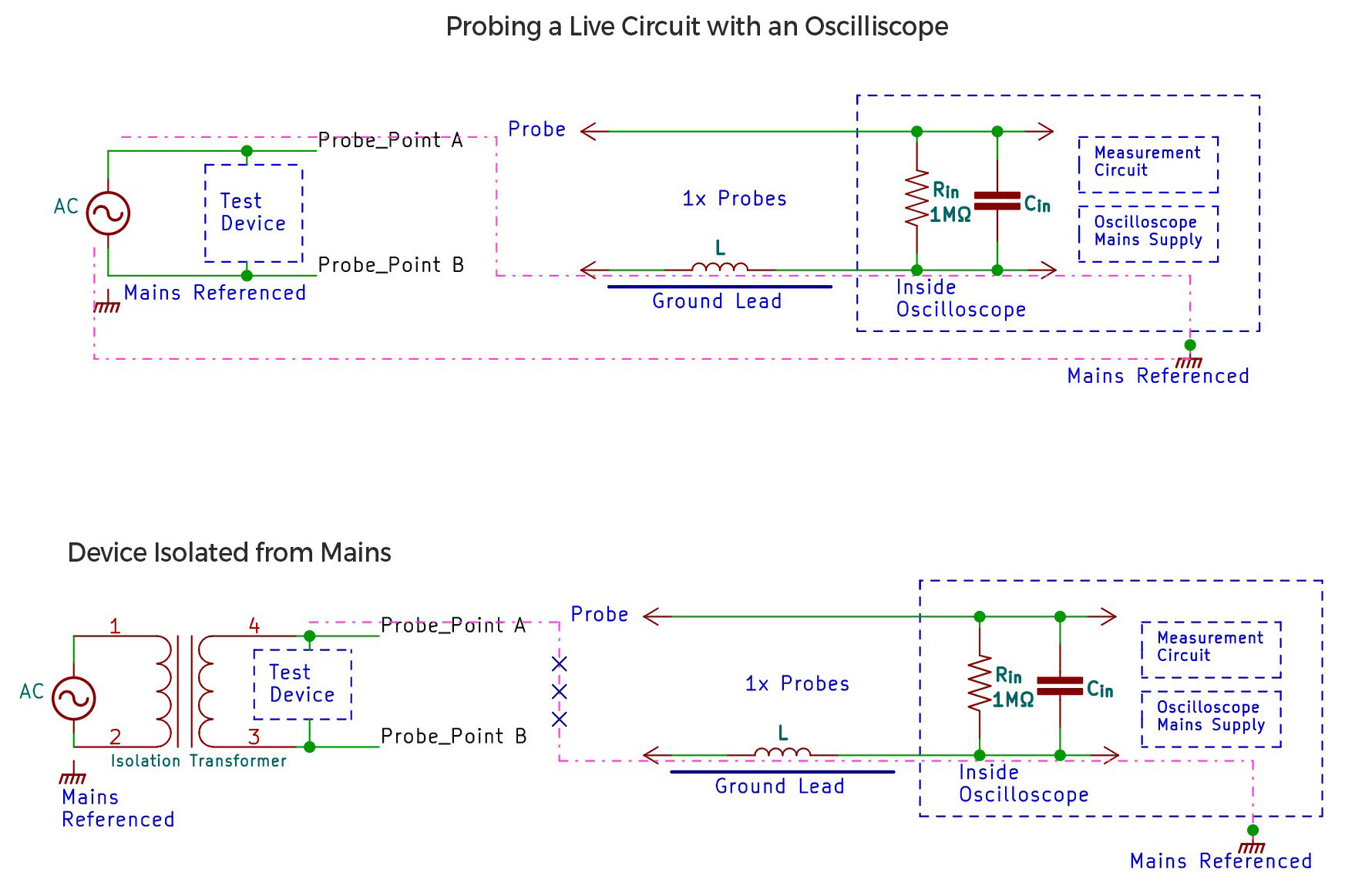
Last week we saw the major drawback of single-ended probes which were mains ground referenced and if you are not careful with the probing you can accidentally damage your scope or circuit under test. Differential scope probes were designed to solve this issue. They are designed to measure voltage differences between two points in a circuit. Think similar to how you would use a handheld multimeter and probe any 2 points. The output of the scope is always the voltage difference between the two probed points.
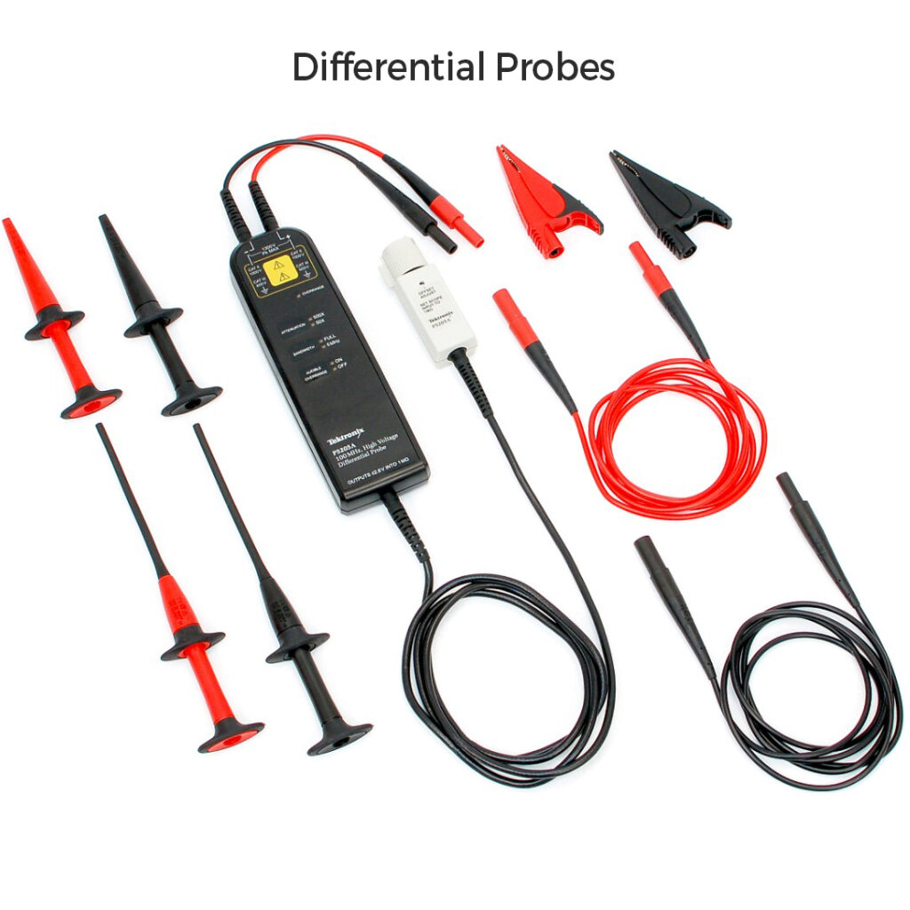
In its basic form, Differential scopes just contain differential opamps in their input side, and the output is single-ended and fed to the input of the scope. Everything we discussed regarding single-ended probes like attenuation, input bandwidth input impedance are all valid for differential probes too. One additional consideration for these probes is the common-mode rejection ratio(CMRR) which determines how much of the noise the probe can suppress that is common on both the input leads. Different manufacturers make units with higher/lower bandwidth and with very varied attenuations in 10x, 50x, or 1000x. The price variations of diff probes are mostly due to the additions in the front end optimizing for higher bandwidth or high-voltage capability (Meaning high attenuation with a resistor divider at input) or even galvanic isolations providing full safety. Note that Differential probes are pricey. You can DIY them too with reasonable specs(check designs online) if you don’t have the budget.
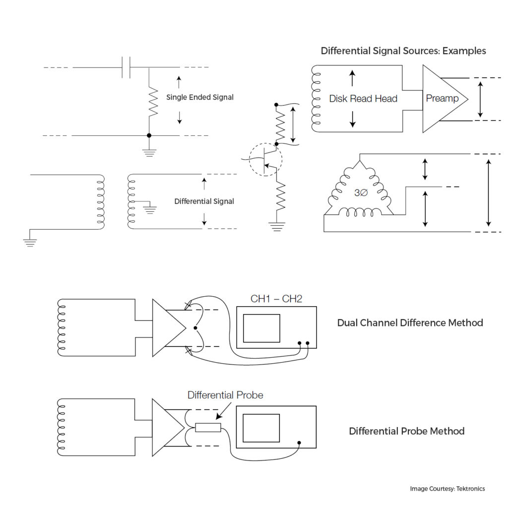
A common misconception among newbies is that expensive differential probes are necessary to measure differential digital signals (USB, CAN, etc.) in a circuit. However, you can utilize two single-ended probes on two channels of a scope, perform an inverted math operation, and subtract the signals to achieve a similar outcome. While the signal quality may not match a dedicated differential probe due to the lower common-mode rejection ratio (CMRR) and mismatched probes, it can still yield satisfactory results. So, make the most of available resources until performance becomes the bottleneck.