Now that we have covered most of the passive probes. Let’s discuss active probes. These probes incorporate active components within the probe housing to amplify, condition, and shape the signals before they reach the oscilloscope’s input which means that it needs an external power source either via special connectors on the scope or via a battery.
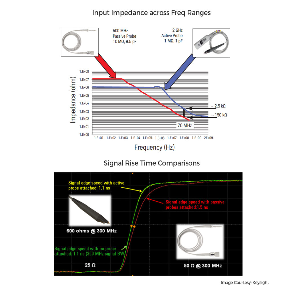
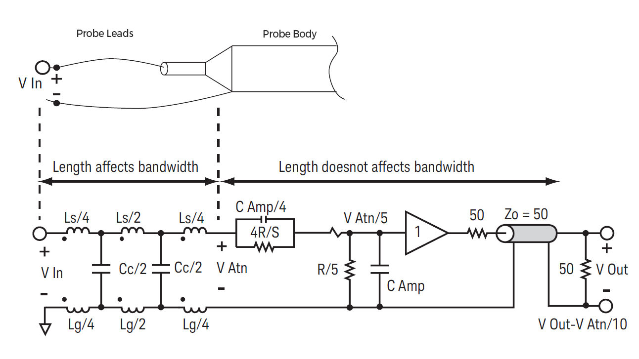
Active probes have a comparatively lower input capacitance around 1pF which means higher impedance and lower signal loading of the circuit under measurement. Flat response across the wide frequency range is what we are usually after and active probes deliver well on that. Bandwidth can be in the order of GHz range compared to a few hundred MHz in the case of passive probes. Lower capacitance also means that you can measure faster circuit rise times compared to passive probes. Internals usually contains a JFET input stage amplifier and signal conditioner. Active probes come with different probe heads with varying probe lengths for different-sized circuit signal measurements.
Active probes are an expensive option to buy considering the superior performance it gives. But you can Google for Active probe circuit designs which will provide you with fairly reasonable specs at probably around 1/10th the price. Remember, choosing the right probe depends on your specific measurement requirements and the characteristics of the signals you’re working with. So do consider them if you want to explore very high signal frequency measurements.