When making production-grade PCB Panels, for some specific PCBs we add something known as Test Coupons. These are structures which are created on a free area of a PCB panel to test a whole bunch of things. It is important to do that on a panel because ideally, you would want to test every panel which comes out from a production perspective(But it’s expensive). It’s imperative because these structures are put through the same manufacturing process as a regular PCB in the panel and any variation on these would affect the rest of the panel too.
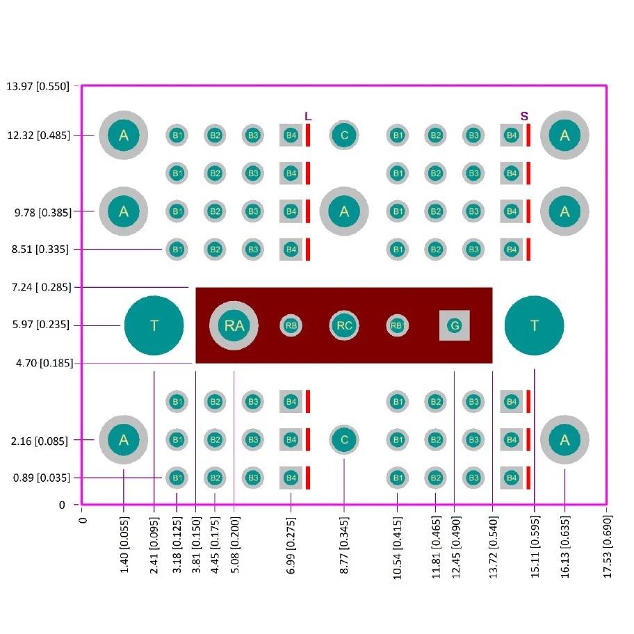
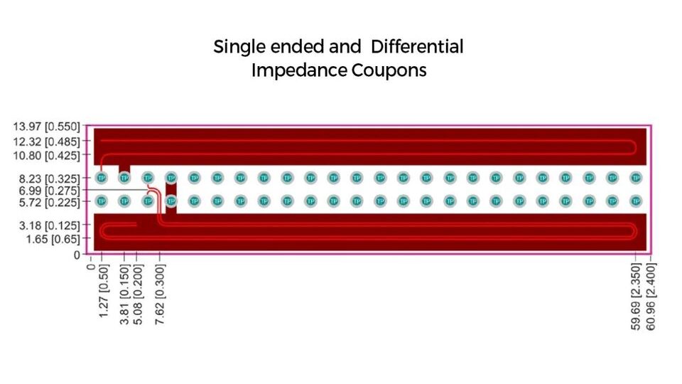
So what are they for? There are different types of standard coupons used to test different things like what is the min drill size which comes out OK, how good is the alignment registration between layers for a large multi-layer board, what is the insulation resistance of the PCB materials used, how good is solderability of SMD pad, how is solder mask adhesion like, What about Via reliability for Blind, buried or filled vias etc. But one of the most important test patterns is to design a coupon to measure the impedance of a particular track on board. These structures once manufactured are used by them to measure the impedance with specialised equipment like a TDR(Will go over this some other day). They have specialised probe points which enable the reading of the impedance. It is very hard to do measurements in an actual PCB design. These impedance profiles help in defining the actual impedance for certain kinds of communication say a 90 Ohm differential for USB or a single-ended 50Ohm line for an antenna feed. By verifying the impedance of a PCB using test coupons, designers and manufacturers can improve the performance of high-speed digital and analog circuits, reduce signal degradation and improve signal integrity.
Coupons are typically test samples that include the most intricate features of your design that are prone to errors. By providing these samples to the manufacturer, you are allowing them to perform tests and avoid any potential errors during production. For more details read up on IPC 2221B:Appendix-A