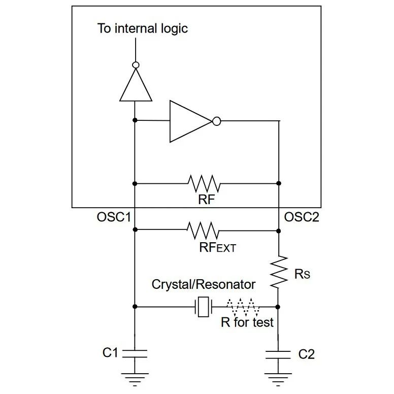
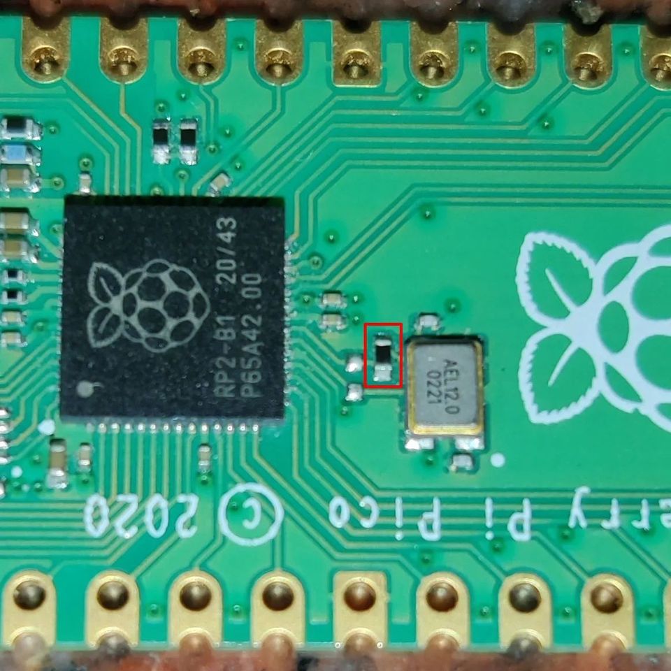
Continuing from the last post, one key element that one of my readers pointed out was the addition of an extra resistor at the output of the Pierce oscillator driver circuit in a uC. It’s a damping resistor and this is something which is not explained in a few newer datasheets and is usually ignored.
A damping resistor is needed primarily to adjust the Drive power of a crystal. Every good crystal manufacturer would add the maximum drive level in its datasheet. This is the maximum power(usually in microwatts) at which the crystal can be driven without damaging it permanently. To measure the driven level, you need to measure the current waveform to a crystal but Measuring this is a hard thing to do in the circuit. One method is to connect another know test resistance and measure the voltage difference with a differential probe to measure current. After the current is measured, test resistance is shorted out from the circuit. This is useful in SMD parts with no space. Another way is to measure it with a current probe in one of the traces. It’s expensive and hard to do on SMD parts so it’s preferred for thru-hole crystals with a probe connected around one of the legs of the crystal.
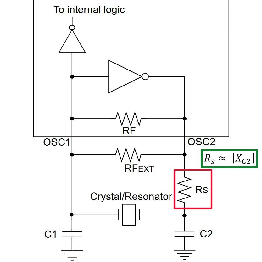
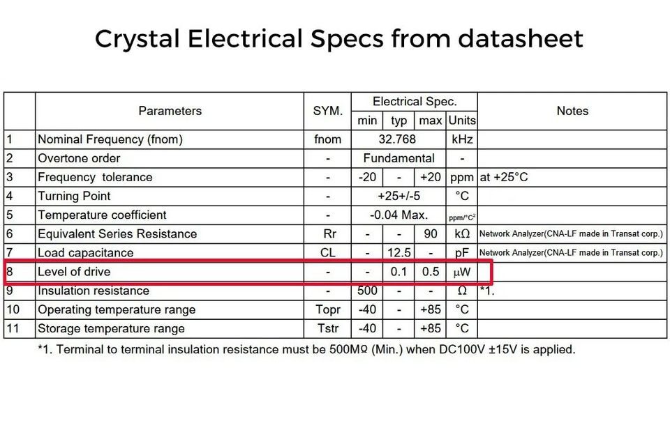
Once the RMS current to the crystal is measured, power is the squared multiplication of this current and the ESR(mentioned in the crystal’s datasheet). This power should not exceed the max value mentioned. If it does, you can try reducing the drive voltage from the uC(By adjusting the gain of the oscillator) or you add a resistor in series. The usual starting value of this damping resistor is equal to the impedance of external load capacitance(at the crystal freq) as mentioned in the figure. Using a normal voltage divider, you will see the drive will be reduced by half. Keep in mind that adding the resistor can add any additional phase shift to the oscillator circuit so you would want to double-check the crystal frequency once again in the circuit. For digital uCs these days, drive values from the Xout pin are set very low and hence you don’t see them in most datasheets.