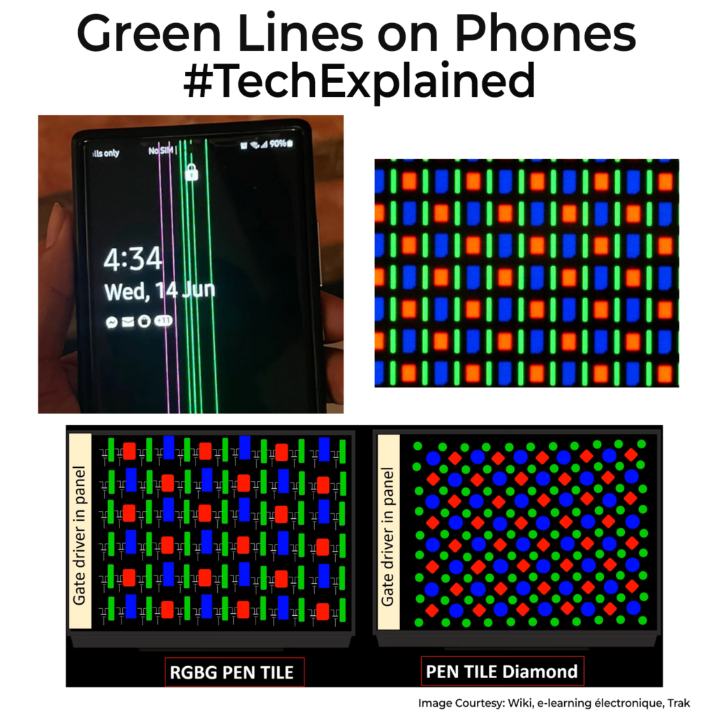
I have personally faced this on a phone a year back. You see them on Samsung, OnePlus, Xiaomi, even iPhones. A thin vertical green stripe on your phone display that never goes away. If you go to service centres, a good chunk of the users would surely be having this display issue. I really have been trying to understand what’s the root cause since then. I looked for official statements on why it keeps happening in the last 1-2 years and have actually found none. Following is my best educated guess on what’s causing it.

Your phone display is a matrix of rows and columns. A chip called the display driver feeds each column. The driver talks to the glass through a flex bonded with an adhesive (called ACF, Check older post for details) full of tiny conductive particles. If any link goes high resistance or leaky, whether on the driver output, chip on film, or the ACF bond, the whole column screws up from top to bottom. That is the line you see.
Why it’s often green comes down to pixel layout. Most phone OLEDs use an RGBG PenTile pattern (Check images) where green sub-pixels are more and form continuous columns. If a faulty column leaks or biases on, the green elements light up in a straight line. Sometimes you see magenta/pink. That’s when the Red and Green pixel lines fail in a column, Red + Green gives you the magenta colour.
My best reason as to why this happens is because of heat and moisture. These accelerate the ACF bond failures. That’s why you sometimes see videos where gentle heating makes the line fade for a moment. Folks usually think green line is caused due to software updates. I would think that’s a classic case of correlation being used as a causation. The only remote link even I can think of connecting it to software would be new settings changed drive conditions enough to expose a weak column, but it’s still a hardware issue.
You will see in some videos on how they use a laser with a microscope objective used to zoom into a column. If they see a break in the line, they will do a strong laser beam weld to fix the line. This also supports the “Localized heating” theory. In some case they scratch the surface of that line with laser then add conductive paste to reform the broken/damaged connections.
Anyway, if you find this issue on your phone, the only way out is full replacement of the display or a 3rd party repair. As I said, above my best guess of what’s happening. If there are any industry insiders who can explain the exact reason, please do, because folks deserve an actual answer.
