Last week we discussed high-side and low-side switching in detail. Today I wanted to extend that with three simple MOSFET cases that you will see again and again in real circuits. I have attached circuit diagrams so you can follow along.
Before that, a quick MOSFET refresher, in case you have forgotten,
For an N-channel MOSFET: Positive Vgs turns it on, Near-zero Vgs turns it off
For a P-channel MOSFET: Negative Vgs turns it on, Near-zero Vgs turns it off
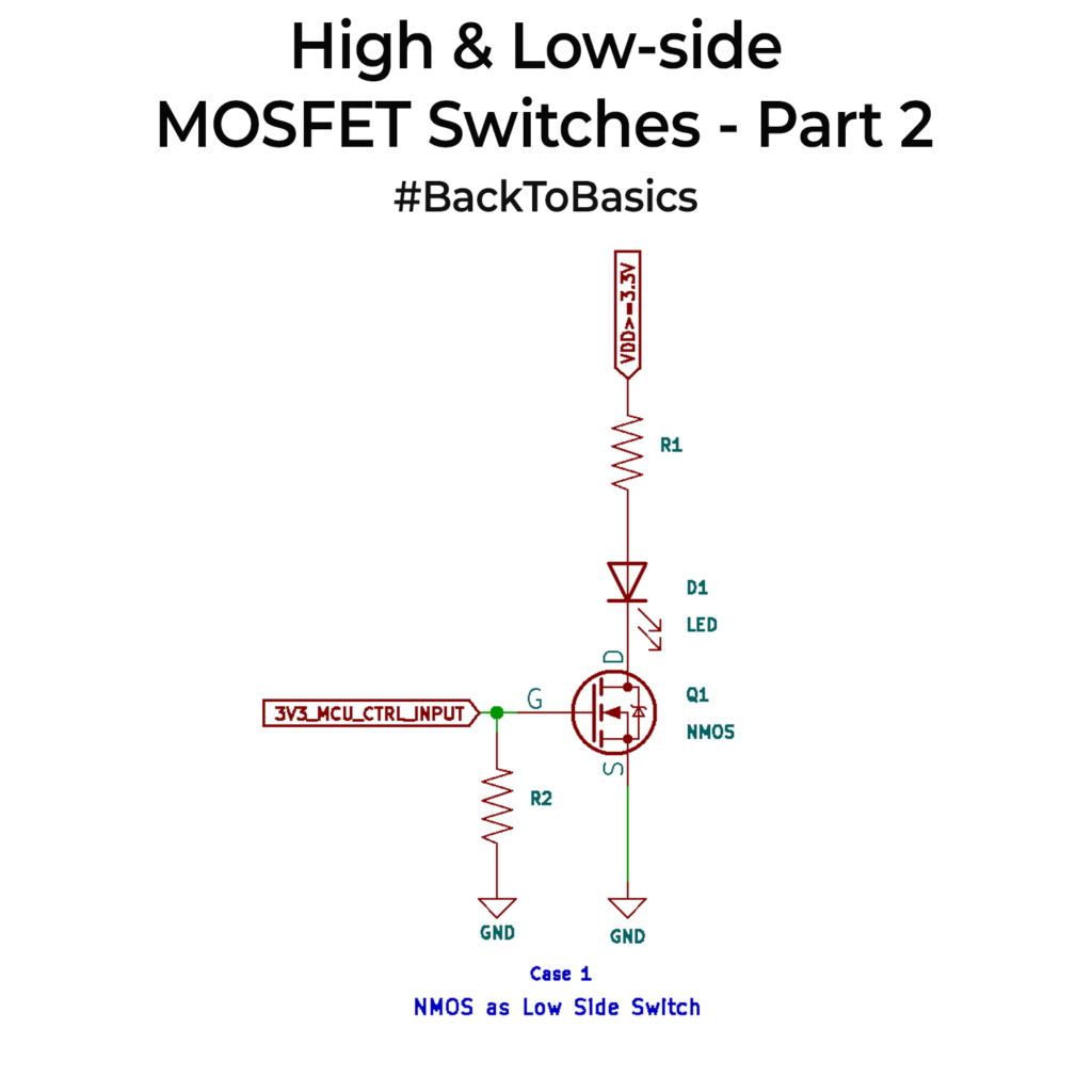
Case one is the classic NMOS low-side switch. The load sits between VDD and the drain, the source goes to ground, and the gate is driven by your MCU(Lets say, 3.3V). When the gate goes high, Vgs becomes positive, the NMOS turns on, and current flows through the load to ground. This is why low-side NMOS switching is the default choice for LEDs, relays, buzzers, and many small loads. The small resistor from gate to ground is there so the gate does not float at reset.
Case two is a PMOS high-side switch when your MCU voltage and VDD are the same, like 3.3V. Here the PMOS source sits at VDD(Not like the NMOS). Pull the gate down to 0V with the MCU and the PMOS turns on. Drive the gate back up to 3.3V and it turns off. This is the simplest way to switch the positive rail when you want the load to keep a solid ground reference.
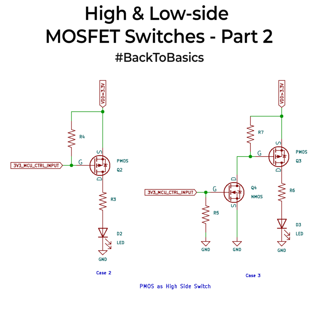
Case three is the one that trips people up. If VDD is higher than your MCU voltage, a PMOS cannot usually be driven directly from the MCU. A 3.3 V output is still lower than a 5V, 9V, or 12V source, so the PMOS may never fully turn off. That is why you add a small NMOS stage. 3.3V from the MCU turns NMOS on, so NMOS pulls PMOS’s gate to 0V and the PMOS turns on. When MCU low turns NMOS off, and R7 pulls PMOS’s gate up to VDD, turning the PMOS off.
Hope these circuits help as a refresher. One practical reminder though. In the LED examples, the series resistor sets current. If you swap the LED for a relay or coil, that resistor is replaced by the load, and you must add a flyback diode across it.
0 Comments
Comments are closed.