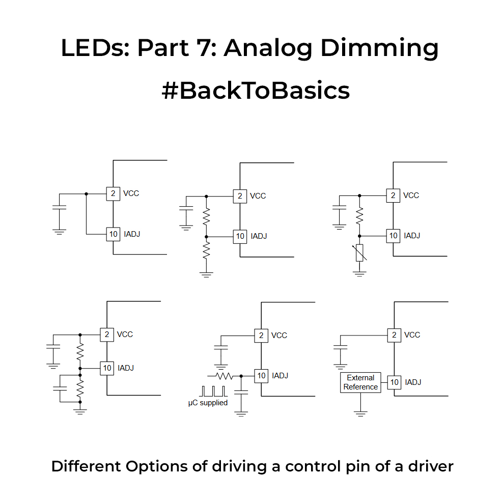
We looked into PWM dimming last time. Analog dimming, unlike its digital counterpart, involves manipulating the continuous current flowing through LEDs to adjust their brightness. While PWM dimming regulates the on-off cycles of LEDs, analog dimming offers a seamless, gradual, and continuous adjustment. The main benefit of analog dimming is the fact that it offers flicker-free LEDs, this is why it’s one more preferred approach for photography applications. You don’t have the hassle of shutter speed sync as in PWM dimming.
Analog dimming is supported by certain LED drivers where you have a dedicated pin that is driven by an analog voltage from a microcontroller or a DC source. These drivers usually have a linear range of operation wherein increasing the voltage on the control pin will increase the current through the LEDs. At the extremities of the linear region you may have sharp jumps in brightness, so always take care of the region of operation if you want a constant light output. BTW if you don’t have variable DAC output to drive the analog pin, you can generate a PWM signal and pass that through a low pass filter whose average output can then be fed to the Control pin.
Since these drivers need to be driven by small analog values, it’s usually recommended to have the driver relatively near to the microcontroller generating the voltage to avoid losses in transmission, esp. in the cases that LEDs are placed in a separate board and you are connecting them with long wires. One main disadvantage of analog dimming is its lower dimming ratio and also the colour shift in the light output because the current is getting changed. So if you want the colour temperature to be constant through its range, this would not be the right topology for you. Choose wisely.
0 Comments
Comments are closed.