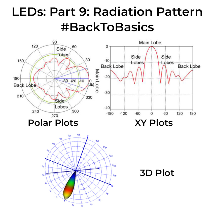
Not all LEDs are created equal! When selecting LEDs, one crucial aspect to consider is their beam pattern. The datasheet section to look into this would be the radiation or luminous intensity chart. It will be a circular polar chart or XY straight line plot (which is just the polar chart stretched out linearly, check images). The graph shows the intensity on one axis and the angle on the other. All that graph shows is how the light is spread out in space and a cross-sectional view of the 3D beam pattern with the LED at the center when you cut it along a particular axis. With this graph, you can understand how the illumination pattern of the LED will be.
Some datasheets opt for simplicity, providing the LED’s beam angle rather than a chart. The beam angle, defined by FHWM (full width at half maximum) is just a fancy way of signifying the angle at which the intensity drops to 50%. This angle influences light spread—narrow beams cover longer distances with heightened intensity, ideal for applications like LED spotlights. Understanding the radiation pattern proves critical when strategically arranging multiple LEDs to achieve desired lighting outcomes.
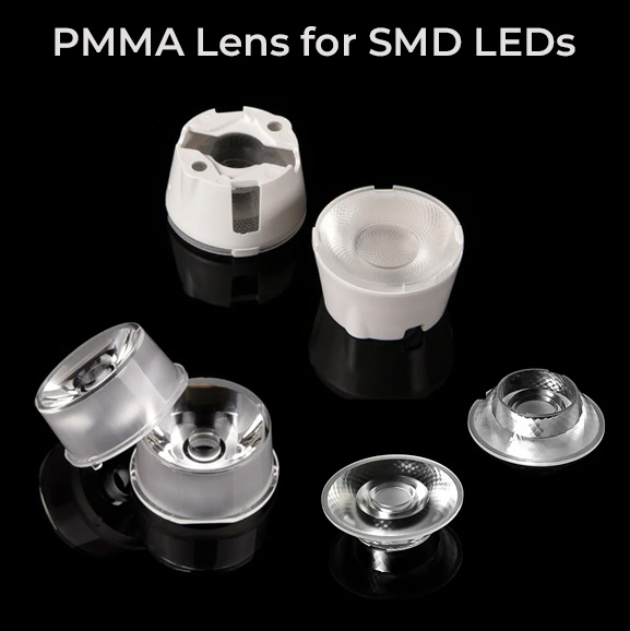
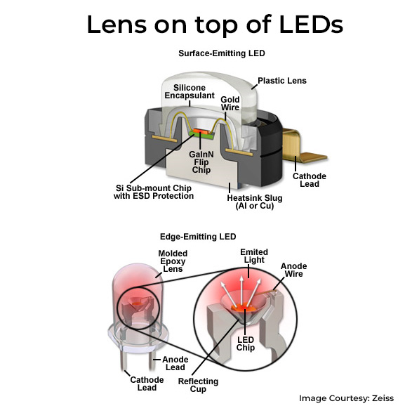
In the realm of SMD LEDs, the physical embodiment of the radiation pattern is done by the tiny transparent lens on top of the LED die. Manufacturers manipulate lens properties to yield diverse radiation patterns. Yet, not all patterns are achievable in-built, prompting the use of mountable lenses. These lenses, often made of moulded PMMA, come with holders and can be fixed on top of LEDs for unique lighting patterns. They’re extremely cheap and are worth considering if you want some unique lighting patterns from your LEDs.
0 Comments
Comments are closed.