Optocouplers are one of the key building blocks of designing an isolation system. They provide electrical isolation between 2 circuits, of which one of them(Not necessarily always) is a high-voltage section. One of the main advantages of optoisolators is their ability to provide galvanic isolation, which means that there is no direct electrical connection between the input and output sides. This can prevent the transfer of electrical noise, voltage spikes, and other disturbances from one circuit to another, helping to improve the overall performance and reliability of the system.
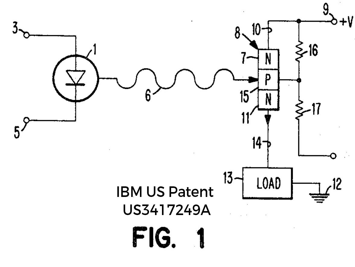
The first versions of the optocouplers were mentioned in the patent in 1963. It consists of an input side LED and a phototransistor on the output side(Check images). When a current passes on the LED side, it glows and that light is used by the base of the phototransistor to detect that there was a change and current flows on the output side. Here the communication is effectively done via Light hence you get electrical isolation from 2 sides. The amount of isolation you get depends on the construction of the ICs and internal spacings. Usually, parts with isolation above 5KV between input and output sides are termed optoisolators. If used for isolation, always think of these as 2 separate circuits and don’t connect their grounds together. It’s a common rookie mistake to avoid.
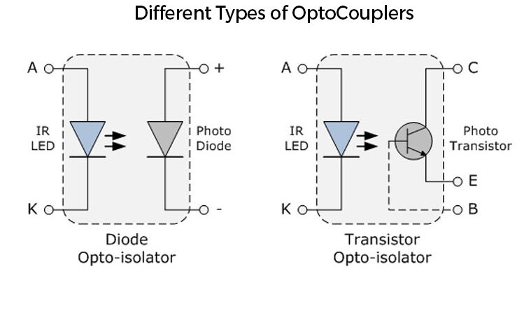
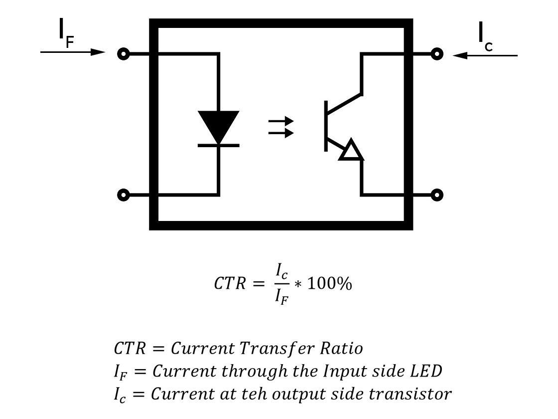
Two major considerations while designing circuits with optocouplers are CTRs and Speed. The current Transfer Ratio is the ratio of the output side current to the input side current. Optocouplers are built to last for a long time, the major failure point is the degradation of LEDs(the light it emits) with time. The current through the LEDs needs to be increased to produce the same result. For digital communication circuits, you have to select units with a higher rate of transfer as it depends heavily on switching times. Always check the datasheets for speed before finalizing the part for your use case. Usually photodiodes are used instead of phototransistors for high-speed.
There are a few more design considerations which I can cover in future posts if there is interest.
0 Comments
Comments are closed.