Today we discuss one of the most basic characteristic of an opamp.
Rail to Rail opamp purely means an opamp whose input and output stages are designed to operate with signal voltages that are very close to both power supply rails under specified conditions. Meaning on a ±5V supply a rail to rail opamp might accept inputs from about −4.9V to +4.9V and drive outputs from about −4.95V to +4.95V into a light load, instead of being limited to something like−4.3V to 4.7V like a non-rail-to-rail opamp.
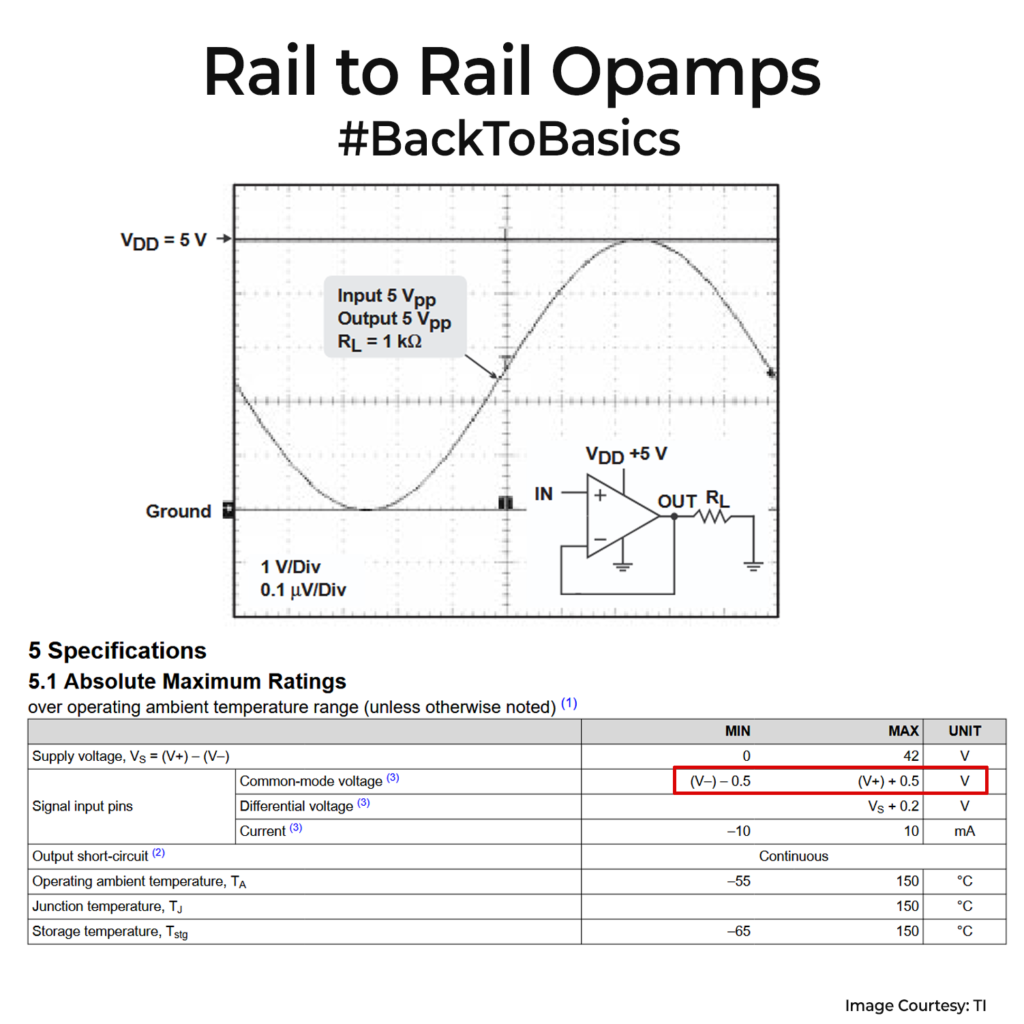
The key spec behind this is the common-mode input voltage(the voltage that is sitting on both inputs) range. If the datasheet says Vcm = V− to V+ + 0.1V, the input really reaches both rails (and a bit beyond). If it instead says Vcm = V− to V+ − 1.2V on ±5V, the input is valid from −5V to only +3.8V, so it is rail to negative rail, not truly rail to rail. Whenever you pick an opamp, this single line tells you how close your real circuit can get to each rail.
You also need to watch the output swing. The datasheet tells you how close the output can get to each rail at a given load. Into 10kΩ it may sit a few tens of millivolts away. Into 1kΩ that gap can jump to a few hundred millivolts.
The rule of thumb I try to follow is to keep signals at least 0.1V inside each rail, unless the graphs clearly prove better. On a 3.3V front end, I budget 0.1V to 3.2V as the working range and treat anything closer as margin.
When you pick a device, filter by supply and package, then read the common mode range and the output swing at your load. Only after that, think about offset and noise. This habit avoids parts that look fine, but quietly clip the last few millivolts.
A mostly unknown fact is that many rail to rail input opamps use two input pairs that hand over near mid-supply, so their worst distortion often appears around mid-scale instead of at the rails.
0 Comments
Comments are closed.