Recently, in a discussion with a few folks, I found that ADC concepts were not that clear. Esp. with regard to the source impedance part. Some were under the impression that you connect a voltage within ADC range and measure, thats it. This might be a very basic thing, but I thought I should explain.
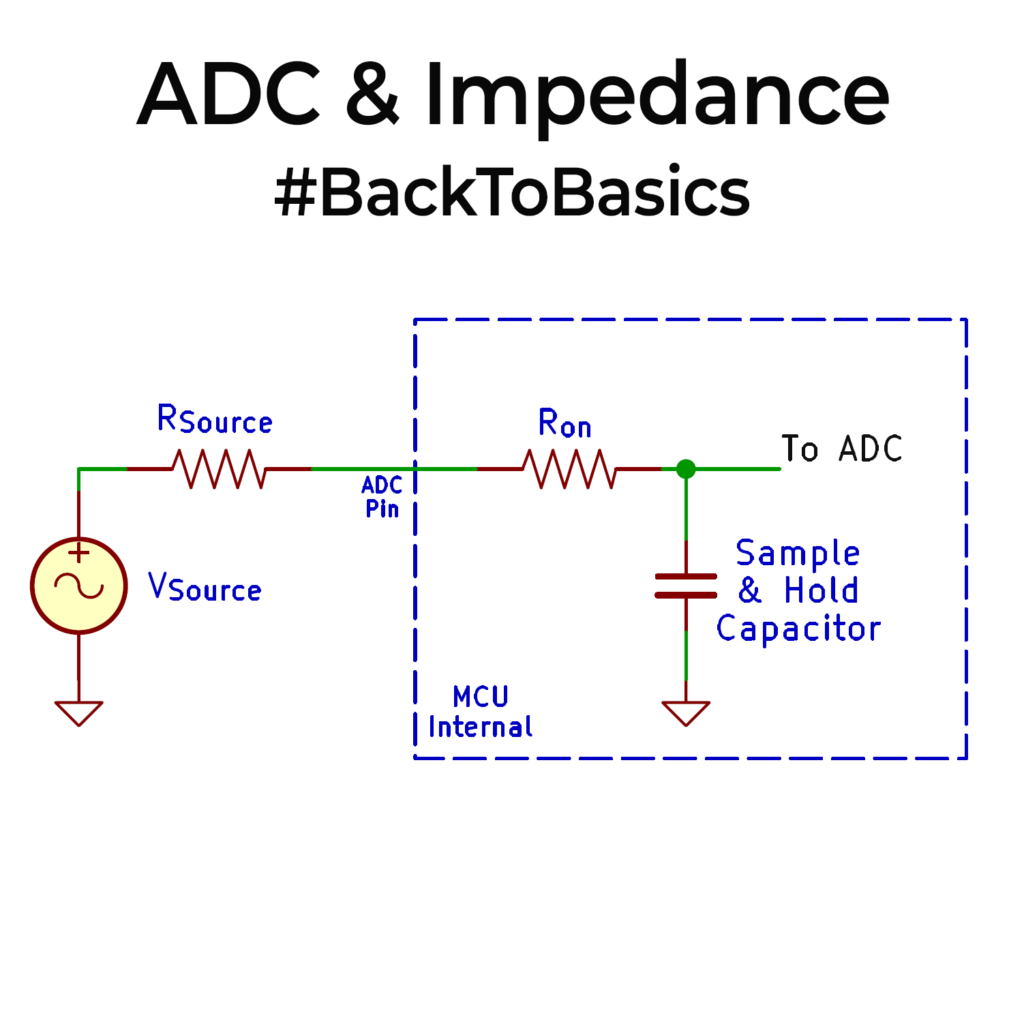
Source impedance is simply the open-circuit resistance seen looking back into whatever is driving the ADC input. An ideal source is zero ohms. A real sensor, voltage divider or source output has some finite output source resistance. That resistance, the ADC’s input resistance and capacitance form an RC low-pass filter. Check images for the equivalent circuit.
ADCs have a sample‐and‐hold capacitance (Approx tens of pF). When a voltage source is connected to ADC, this capacitor charges through the source resistance and an internal switching resistance (approx 1-2kΩ). This RC circuit needs a finite time to rise up. If you have a 2bit ADC for the last bit to settle, it would take approx 10x the RC time constant. To put it approx numbers, let’s say Rsource=1kΩ, Ron = 1kΩ, C= 10pF, RC time constant is 20ns, 10x that would be 0.20us. So you need to sample and take values only after this settling time for the LSB, else it will give you are wrong reading. This becomes a major factor if you are taking only 1 ADC reading of the sample and then going away. If that value is not settled, you get a wrong reading. Especially applicable when sampling fast changing AC signals. Now if Rsource is larger, say from a large MΩ voltage divider, your sampling time is going to 1000x this number. So always aim to keep source impedance less than 1k or so if you can afford the current.
What to do if you can’t? Then use a buffer so that your flow will be,
Sensor ->(High-Impedance) -> Op-amp (Unity gain buffer) -> (Low-Impedance) -> ADC input.
This guarantees the ADC always see a low-impedance source because of the op-amp and your input is effectively shielded.
Please do take care of the source impedance case. There is lots to discuss regarding ADCs. If there is genuine interest, I can spend some time creating a series in the future. Do let me know.