Let’s discuss this one today. Many people that I know don’t even know that these exist.
An isolated DC-DC converter moves power from one domain of your board to another without a galvanic connection. Input and output don’t share a ground. Energy couples through a tiny transformer, so the secondary side can float. It breaks ground loops, reduces conducted noise, and limits how faults on the primary side propagate downstream. So you can use this in your circuits where you want to transport power and be potentially safe. Think about the cases where you might have High voltage on one part of the circuit and low voltage on the other part & you want separate them.
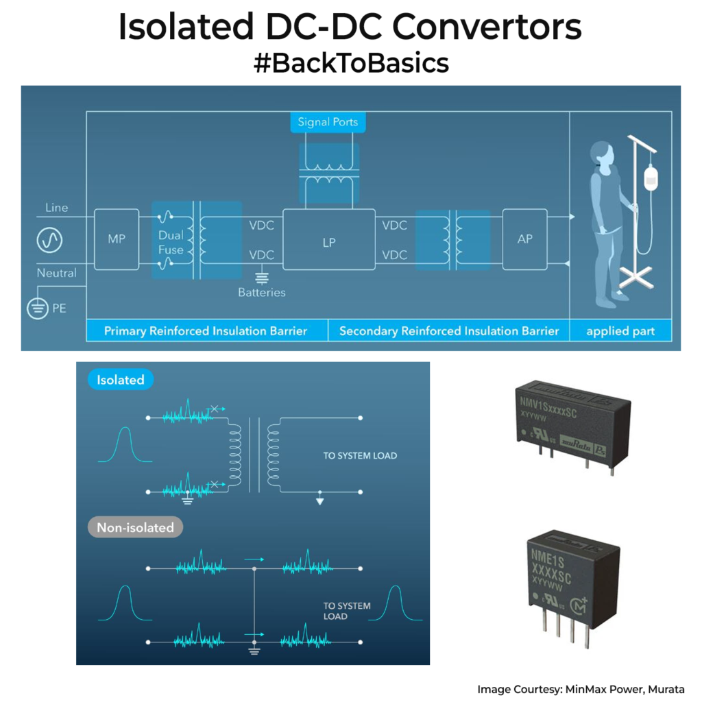
So how does it work? A MOSFET switch chops DC into high frequency to drive a small transformer. The secondary rectifies and filters it back to DC. Flyback stores energy while on and releases it when off.
Typical use cases where you would use them would be for sensors front ends and 4-20 mA loops, RS-485 or CAN nodes and products that must meet medical or industrial safety. You also use it to create a floating rail for level shifting. One great part is you can create negative or positive output as its floating output.
These converters are usually available as modules, and it’s worth buying rather than you spending the time designing one from scratch to use(unless you have enormous numbers). For different power ratings ranges, you will find ready-made options in SMD and through hole parts. Murata, TI and Recom are few of the players around. Make sure you size the module based on the output requirements for current and voltage. These modules don’t have very high efficiency. Typically, expect them in 60-85% range.
Anyway, keep these modules in mind when you plan to build a product which would need safety and isolation.