Back to Basics: Capacitor DC Bias Effect

MLCC(Multi-Layer Ceramic Capacitor) which most of you are using in your circuits(The usual SMD type) are divided into Class 1(Dielectric: Titanium Oxide) and Class 2(Dielectric: barium titanate). These Class 2 capacitors have problems that most of you never would consider. The capacitance value drops very drastically with the applied DC bias voltage to it.
DC Bias Capacitors

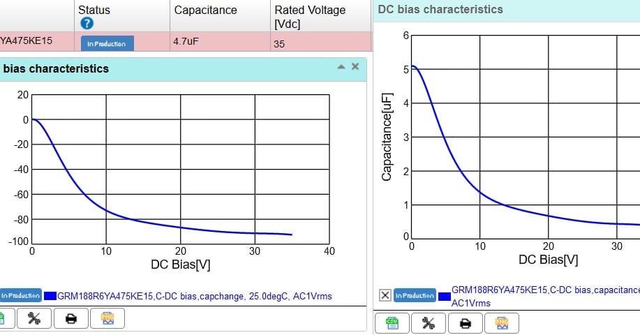
Take a look at the graph of a standard Murata capacitor(Nominal Value: 4.7μF rated for 35V). Now as the DC voltage applied to the capacitor is increased, you can clearly see that capacitance drops close to 0.5μF when it’s near its rated voltage. This will be a major issue if you are using this capacitor in circuits where capacitance value is critical like for timing or filtering. The effective capacitance will totally screw up your results when you move from the paper design to the physical board. So please consider this when you design next time. For critical applications, try to use Class 1 capacitance which is much more stable. Class 2 caps show this behaviour because of the Barium titanate dielectric used to make them.

One way to counter this problem is to use capacitors that have a rated voltage much more than what is needed for critical applications or by having the same capacitances in parallel to increase the effective capacitance to the nominal ones you design for. For MLCCs used in critical parts of your circuit always, ALWAYS, buy from reputed capacitor brands where these graphs are provided and not from knock-off unbranded ones. Else it will come back to haunt you later on and you wouldn’t even know this part is the culprit. Capacitor Package Size and its values also have an effect on the amount of value degradation. So please refer to datasheets thoroughly before selecting.
PS: Capacitors and things associated with it is a big rabbit hole in themselves. It would itself need an entire series of posts. I can definitely consider this for the future if there is enough interest in these basic topics.
If you liked the post, Share it with your friends!

Back to Basics: Inductor Rated Current vs Saturation Current

Saturation Current

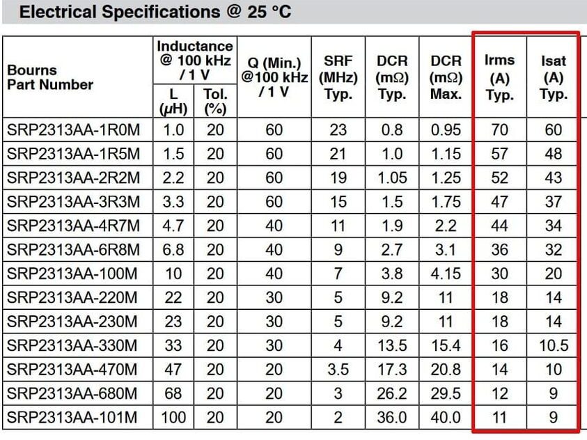
When choosing inductors in your design, one of the most confusing aspects is the rated current and saturation current values(there are other alias names like Irms, Itemp etc) mentioned in the datasheet. In older datasheets, these are rarely explained. What should you choose as the upper limit current rating for your inductors? Sometimes saturation currents are more than the rated current. It becomes a troublesome design choice till you understand what these actually are.

Rated current is the amount of current that can go through an inductor to heat it up by a fixed temperature value from the ambient(usually 40°C). Meaning if the rated current is 3.5A, once this amount of current is passed through the inductor and once a steady state is reached, the temperature of the inductor will be 65°C if the ambient temp is considered as 25°C.The saturation current mentioned in the datasheet is the current that when passed through the inductor, it becomes “saturated” and starts losing its inductance value by 20-30% of the original value.

So when choosing an inductor you can push the current values to maximum saturation current before inductor values start to drop(Ideally you shouldn’t but you can). You can pass more current than the rated value through an inductor, provided, you can give adequate cooling for your inductor. It’s given in a datasheet so that you don’t exceed the operating temp range of the inductor. If you are using the inductor in a use case where your ambient temp is 70°C, at rated current, the inductor temp will be 110°C which might be beyond the operating temp of the inductor packaging and it will stop working altogether.

So choose your inductors carefully. It’s not always about the inductance values alone.

If you liked the post, Share it with your friends!
1 28 29 30 31 32 34