Back to Basics: Equivalent Series Resistance (ESR)

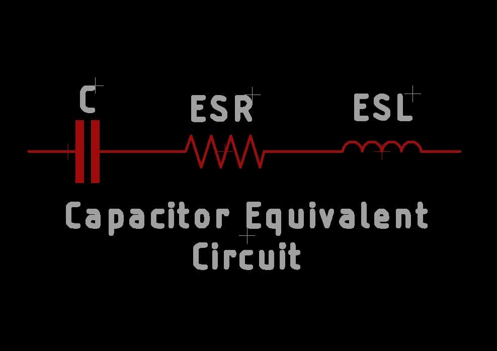
Capacitor Equivalent Circuit

In real life a capacitor is not really a capacitor alone, it will have an internal resistor and an inductor. This resistance is what is known as an ESR. We ideally want ESRs to be tending to a low value as they are the primary cause of switching losses in a capacitor. These vary with the temperature and type of construction of the capacitors. Electrolytic caps usually have higher ESRs.

So why should you care about ESRs in your design process? Usually large electrolytic caps are used as bulk storage to maintain a voltage rail in the input of a system(To avoid voltage drops at high frequency). Now you have a high ESR capacitor, it won’t be able to deliver the charge to the system quickly because of the series losses in the ESR. That in turn will heat up the capacitor to potentially dry up the internal dielectric material as well. So in order to reduce the switching losses, try to use good quality capacitors with lower ESRs in your design if you have the budget for it. One trick is to use multiple caps of the same ESR, in parallel, to effectively reduce the ESR. High ESR caps reduce the longevity of your design with use.

ESRs are mentioned in the datasheets and is specified by measuring the resistance at a frequency of 100KHz. It’s done with an ESR meter which injects a 100KHz low voltage signal and measures the voltage across the capacitor to estimate the ESR(As at high freq, the capacitor will be having negligible impedance). This voltage is converted to resistance to give you the actual ESR of the capacitor being tested.

For circuit debug/repair work, ESR meters are a good tool to have because they can be used to measure ESR in-circuit(Without removing the part from PCB). If the ESR meter reads high(Usually bulgy electrolytic caps, but remember they need not be always bulgy), that’s a bad cap and you can remove that specific capacitor to replace it with a new one.

If you liked the post, Share it with your friends!

Headphone Volume Control DIY Fix

View this post on Instagram

A post shared by Amaldev Venugopal (@amaldev.000)

In these days of wireless headphones, I am still a fan of wired ones because of their longevity and not having to recharge them every couple of days(Also after a few hundred charge cycles, the battery loses its capacity). I like the ones with a built-in microphone and slider volume control. Usually, after a year or so of its use, most wired headphones would have the problem of mismatched sound on both ears and when the volume slider is moved, there is always poor volume progression, followed by sound cracking.

Mechanical sliders inline in your headphones are resistance potentiometers that have a wiper arm changing the resistance when you move the knob. What happens after some amount of use is that the wiper contacts get dirty and the resistance values won’t increase gradually. It makes contact only at certain points(Hence the cracking/popping sounds).

A quick fix to this problem which always seems to work for me is to take a high-quality Isopropyl Alcohol(IPA 90%+ concentration) and spray down the contacts. If there is a chance for you to open the plastic enclosure it will be great to open and clean it. Most of the time as shown in the video, it will be ultrasonically welded and you won’t be able to open it without breaking it. In that case, find a small opening next to the slider and spray the IPA. Make sure you move the sliders back and forth quickly a few times to properly clean the contacts. That should fix your problem. Good quality IPA evaporates fast and won’t leave any residue.

PS: Don’t use any oil-based lubricants for this if you can’t find IPA as it will damage your carbon film potentiometers. Another alternative is to get professional-grade electrical contact cleaners.

Happy Listening. 🙂

If you liked the post, Share it with your friends!
1 29 30 31 32 33 34