SIDAC is a specific type of thyristor that is designed to switch on when the voltage applied to it reaches a certain threshold. It is often used in high-voltage applications, such as in power distribution systems. To understand how a SIDAC works, it’s helpful to think of it as a switch that has three states: off, on, and holding. When the voltage applied to the SIDAC’s gate terminal is below its threshold, the SIDAC is in the off state and does not allow current to flow through it. When the voltage applied to the gate reaches the threshold, the SIDAC switches on and allows current to flow through it. Finally, once the SIDAC is on, it remains in the holding state until the current flowing through it drops below a certain level, at which point it switches off again.
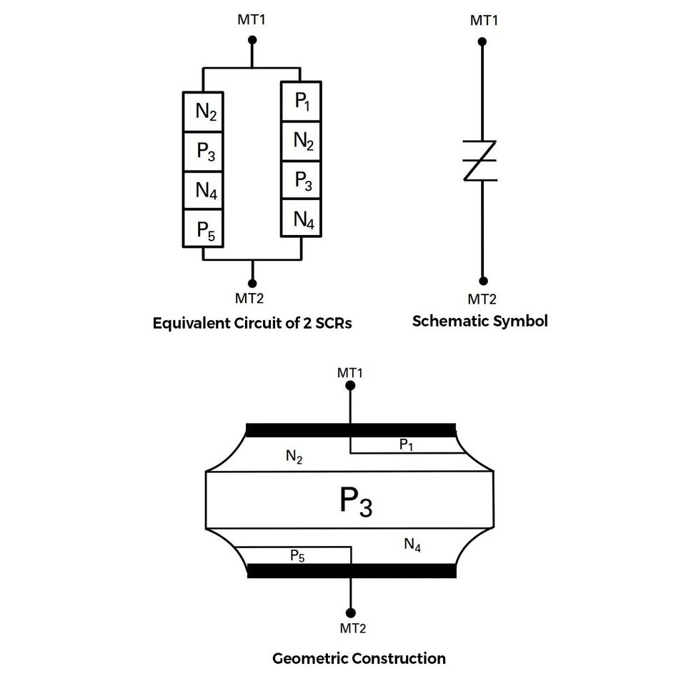
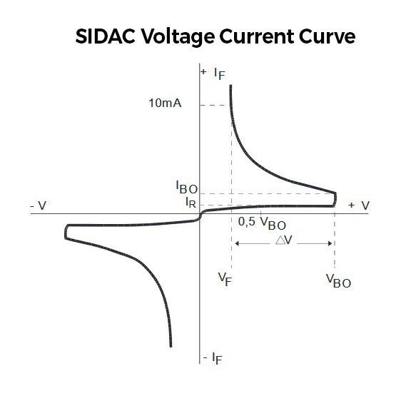
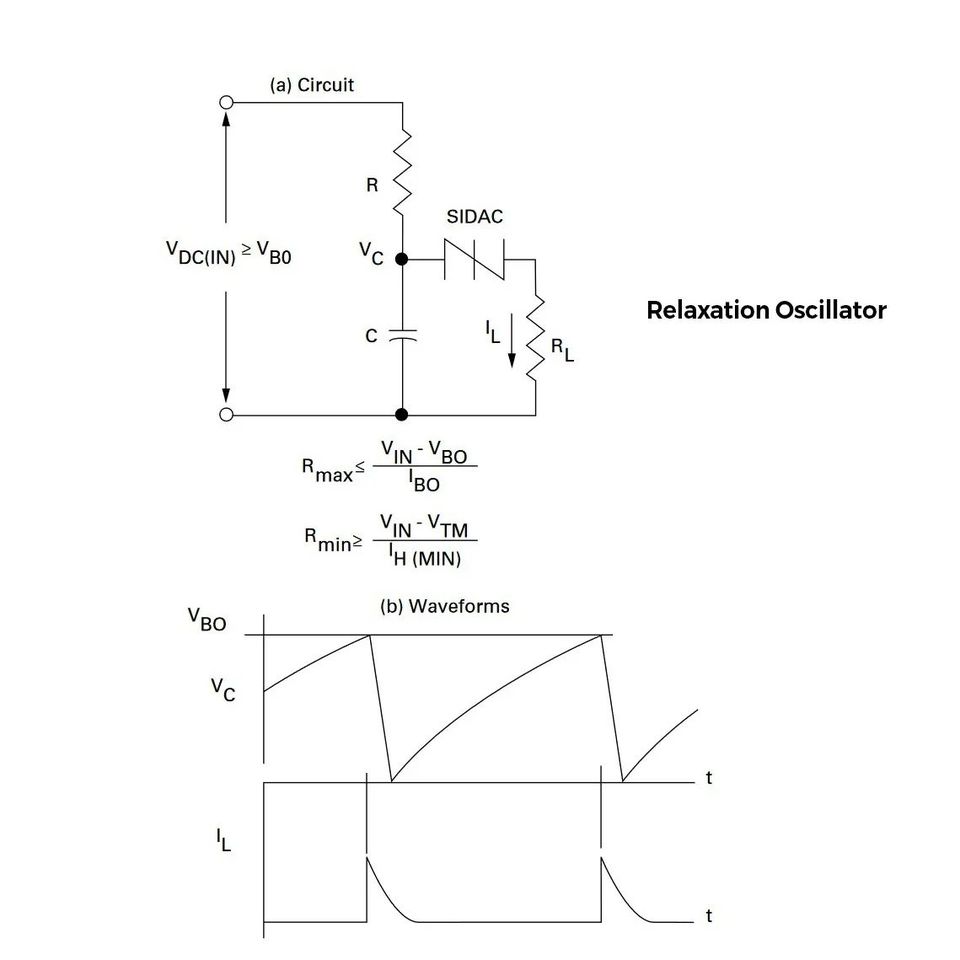
It is similar to a DIAC but with higher voltage breakdown regions and current-carrying capabilities(SIDAC = Silicon Diode for Alternating Current). Its a 5-layer PN junction device as shown in pics. Once breakdown voltage(VBO) is reached, it goes to a negative resistance region when current conduction happens. SIDACs are used in relaxation oscillators which are used to create non-sinusoidal waveforms like triangular waveforms. Here a SIDAC is connected in parallel to a capacitor. Initially, the capacitor charges up and when the voltage reaches the threshold of the SIDAC, it makes the SIDAC discharge to obtain your sawtooth waveform whose timing can be adjusted via RC time constants.
Now for the twist, the first paragraph wasn’t written by me. It was generated automatically by the Chat-GPT3 AI service(built on 175 billion parameters). I just gave it an input to explain what a SIDAC is and it gave me the first paragraph as is. An AI model gave me an answer instantly which would have taken me a couple of hours to read up from different papers and books. I am totally mind-blown by what can be done with the tool. It’s going to be used as a companion tool to improve your efficiency drastically(Think GitHub CoPilot). It’s not correct always, it usually gives plausible-sounding but sometimes incorrect answers. If I ran it a few times, I can clearly see it getting some stuff wrong. But possibilities are endless with this tool and I can’t even imagine what it will become 3-4 generations down the lane. All the low-hanging jobs in future will be taken over by AI, in a similar way to how automation killed a large part of manual labour. Start upskilling yourselves in whatever field you are in or you will struggle in a decade or so.