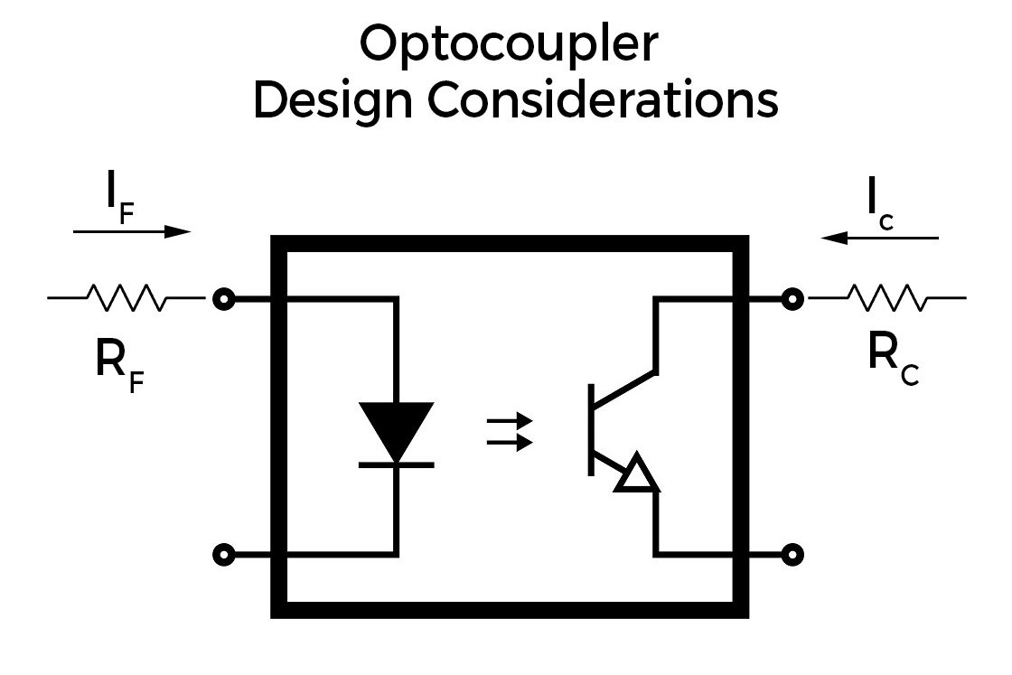
A few folks from the last post wanted to know more about the design considerations of optocouplers. Let’s briefly go over them. The important consideration is the forward LED current, If. Its current-limited by a resistor Rf, which is straightforward to calculate based on the maximum current which can pass through the LED from the datasheet and the LED forward voltage. Standard KCL will give you the current. The question here is should you be driving the LED at its max current? Problem is that LED driven at its maximum current loses its brightness over time. For any LED application where it needs to last a long time, a common rule of thumb I personally follow is to limit the current through the LED to half the maximum current possible. I don’t push the LED to its limits and derate itself. Yes, this means that I leave a larger margin which can effectively increase the cost but it can help the circuit perform normally over a long time.
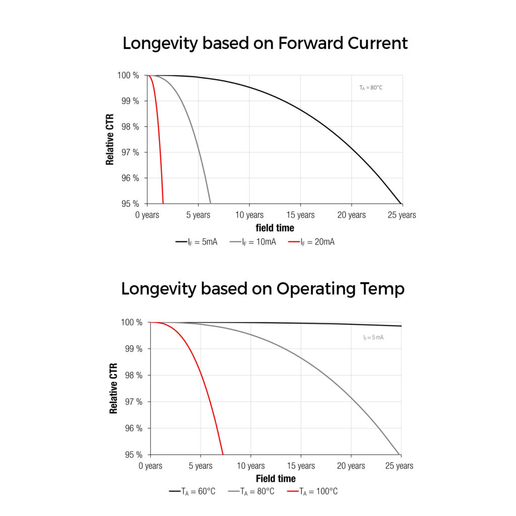
The second is ambient temperature. Like the current through the LED, choose optocouplers based on the operating temperature. It does have a severe impact again on the lifetime failure of the device. Obviously, lower is better for longevity. In good datasheets, you will find a curve which shows current and temp deratings.
The next consideration is to figure out what sort of isolation voltage you need from the input to the output. It heavily depends on the voltage applications you use this device. The important parameter in this is also the creepage distance between the input and output side to prevent the arcing over the isolator for higher voltage application.
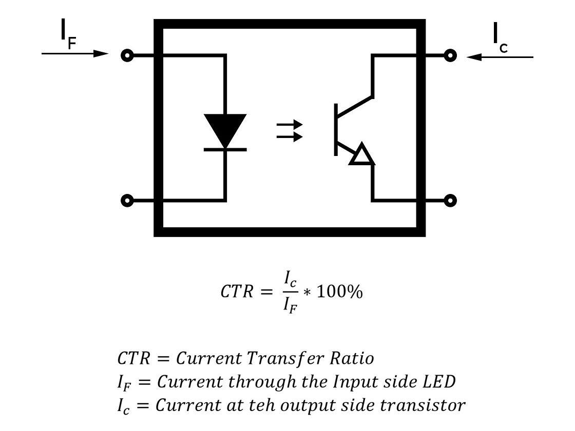
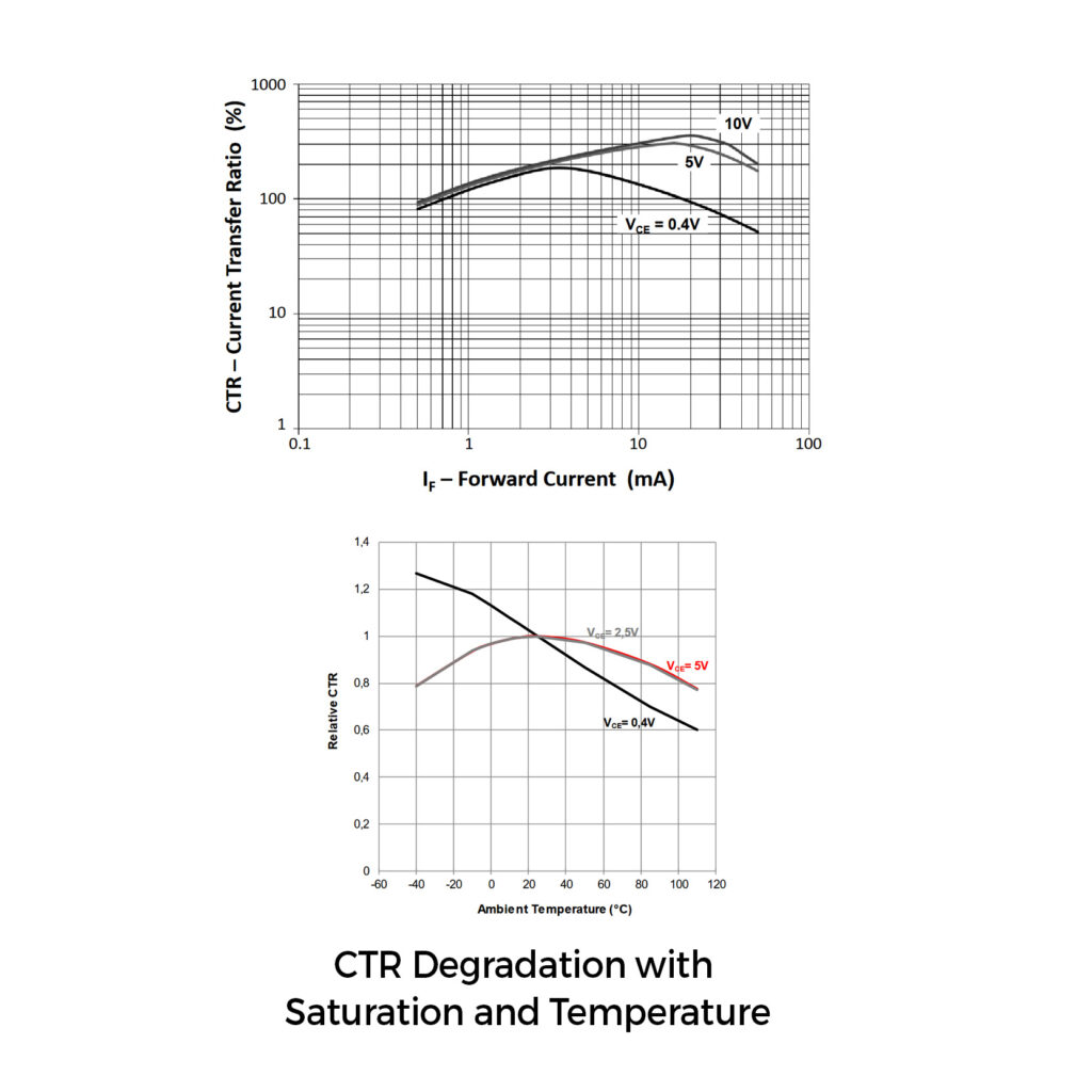
The current Transfer Ratio(CTR, refer prev post for more) is another parameter in design. Its ratio of output to input current. For analog applications, try not to push the transistor to saturation by increasing the If current. If it saturates, the input current has relatively no role in determining the output side current(It will only be decided by the max current limits on the output). On datasheets, you will see CTR vs If curves, which increase till a point and then drops down. Usually(not always) you are looking for a high CTR to transfer max current at the output for a small change in input.
I have only glanced through a few points for more read App Notes ANO006(Wruth, Agilent’s OptoCoupler Design Guide and Toshiba’s Photocoupler App Note.