After the last week’s post, a few of you had doubts pertaining to bitrate and bandwidth. This by itself is not a confusing topic but it’s made confusing by the use of the same word in different contexts to mean different things. The word “Bandwidth” refers to different things in different fields (I don’t why, but it’s just the way it is).
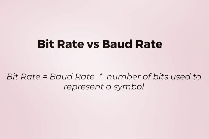
From a network & digital communication engineer’s POV, bandwidth actually refers to the maximum amount of bit rate(bits per sec) a communication channel can transmit at a time. Each communication channel can have inherent restrictions on how much data it can transmit. Think of a home internet optical fibre link. This channel can potentially physically transfer let’s say 1Giga bit per sec. But let’s say you are subscribed to a 100Mbps plan with your vendor, so even though your overall bandwidth is large, the max bit rate you can transfer based on the limits is 100Mbps. Bandwidth in this context(it can be 100Mbps or 1Gbps based on how you want to define it) is just the upper limit of the information bit rate in a communication system.
From an analog communication engineer’s POV, bandwidth refers to the frequency range in Hz. It represents the range of frequencies that a signal occupies in the frequency domain. Take Bluetooth for example, It operates in the 2400 – 2483.5 MHz range with an overall bandwidth of 83.5MHz. This range simply says that whatever signals you send in BLE should lie in this range. This range is again divided into 40channels with each having a bandwidth 2MHz so that multiple people can communicate in this same band at the same time. 40 X 2 = 80MHz. The remaining 3.5MHz range is used as a guard band on the lower and upper side so that it wouldn’t interfere with other communication systems.
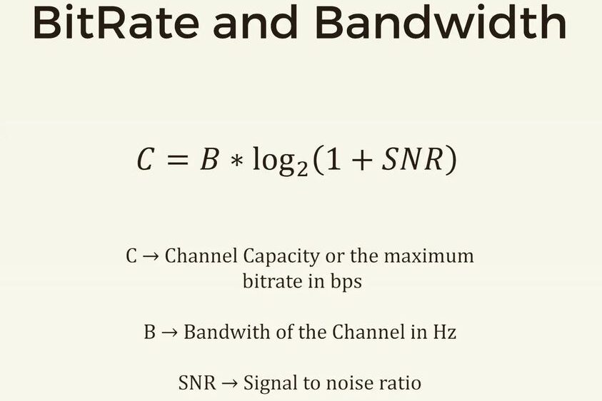
Now to tie these two domains together, Shannon defined an equation which is shown in the images. It defines the maximum upper bound data bit rate that you transfer using a signal with a particular bandwidth. The overall rate of info transfer depends on the analog bandwidth (larger bandwidth means more data can be pushed). It also introduces the Signal to Noise factor which limits this rate. All its saying is if the noise is high, the meaningful data rate will be low.
I hope this clears up the confusion about using the same term for different things. The problem is not with the terms, but mostly with how we pick these up in colleges. You have different Profs teaching you analog and digital communication courses and each defines in their own way. As a student, you wouldn’t be able to put the two together unless you abstract this infos out and start seeing how these are implemented in real life. Always be curious and ask questions. Understand that your learning should never ever stop for you to keep growing.