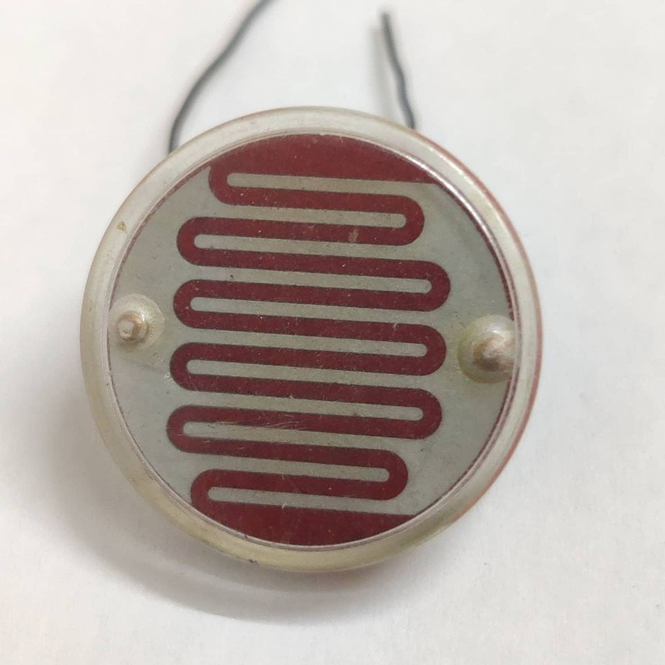
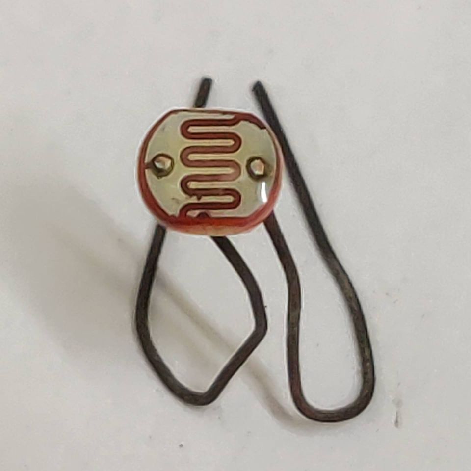
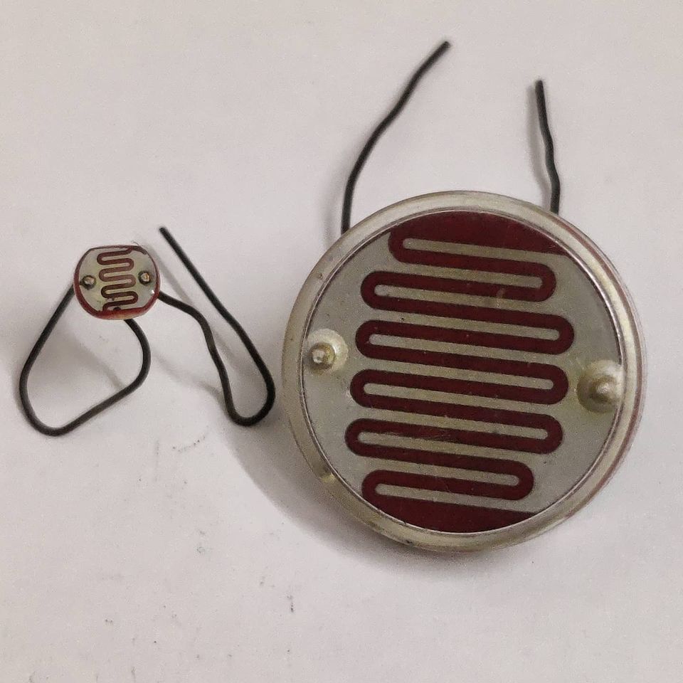
Cable Ferrite Beads

USB Ferrite Cable
Snap on Ferrite Core

Most of you would have seen these thick cylindrical parts embedded in USB/Power/HDMI cables around your home, right next to the ports. These are ferrite cores. Basically made of a ferrite material and consists of 2 halves clamping together around a cable. It forms an inductor and is used to suppress high-frequency noise in a cable. You will mostly find it in good-quality branded cables. This becomes important in consumer electronic cables to prevent radiated emissions, to and from the devices it connects.

There are snap-on cores of different dimensions(Hence different impedance to the high-frequency signals). These become very useful for EMI engineers to suppress cable noise and pass the electronic certification. You try on different snap-on cores(sometimes looping the cable inside the core a couple of times) and whichever helps you pass the test goes in the final product(Just the ferrite core part gets embedded in the cable). Saves you a ton of time(and money) while testing in the EMI test labs.

If you liked the post, Share it with your friends!

Capacitive Dropper

Probably one of the most common and cheap power supply circuits used to power low current applications directly from AC. You would have used these for sure at your homes in LED night lamps, fan regulators(Maybe a future post when I get time) or any of the cheap gadgets that plugin directly to your mains AC supply. The elegant part of the circuit is that it removes the need for a bulky transformer and can be built with very few components.

LED Bulb Teardown
LED Bulb Teardown
Circuit Schematic
LED Schematic with a capacitive dropper

The pictures are of LED night lamp which plugs into mains directly. It consists of a higher wattage in-rush current limiting resistor(R1, during turn ON of the device, so as to not let a large current through initially), and a capacitor(C1) in series with the mains(Instead of another resistor). The capacitor is designed to give impedance without losing power as heat at 50Hz. The resistor (R2) is a large wattage resistor which acts as a bleeder resistance to discharge the capacitor when the device is OFF(To avoid shocks if you touch it). The overall circuit has a poor Power factor but has low active power consumption. This is basically all because of the capacitive dropper circuit section.

The rest of the circuit is a four-diode bridge rectifier to convert to DC, and an electrolytic capacitor(C2) to smooth the DC at the output. This is really not needed if you really wanted to skimp on parts. LEDs will work fine on AC(you may see flickering though sometimes).

If you liked the post, Share it with your friends!
1 70 71 72 73