Today, let’s talk about Local Interconnect Network(LIN). I believe it’s an essential but yet often overlooked communication protocol in automotive tech because of its big brother CAN.
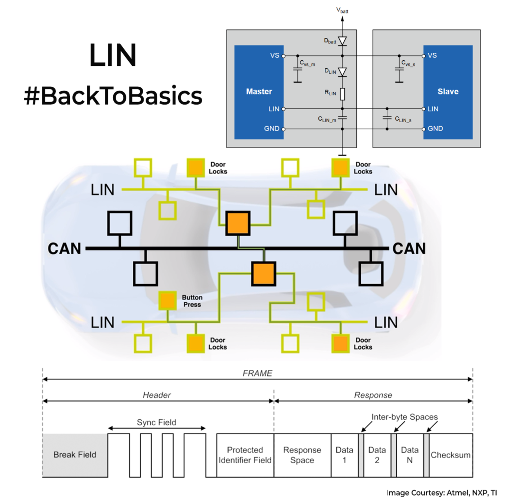
LIN came in the late 1990s when automotive manufacturers needed a simpler, cost-effective solution to complement CAN. While CAN was great for critical tasks like engine control or braking. But for simpler tasks, CAN was too complicated and expensive. This is exactly where LIN shines. It operates on a single data wire (Data & GND) serial communication, making it simpler and cheaper to implement. LIN transmits at speeds up to only 20kbps which is more than enough for non-critical tasks like controlling windows, mirrors, seat adjustments, and wipers. Why use & waste the CAN bandwidth for these routine tasks?
Its architecture consists primarily of one master node and multiple slave nodes(upto 16). The master node initiates communication by sending a header; slave nodes respond based on predefined data frames. LIN has a self-synchronization feature, meaning slave nodes synchronize automatically with the master’s clock every time a message is sent in the header frame. Hence, there is no need for additional timing signals. Since communication protocol is not complex, it’s usually handled in the microcontroller and doesn’t need a dedicated controller like CAN.
The uC’s output is level shifted by specific LIN transceivers for transmission/reception in the bus. The physical layer bus voltage can be between 9V-30V, depending on the IC. They require pull-ups like I2C, but it might already be built into the IC. Although speed of communication is low, you would need to keep the bus capacitance under 10nF for good signalling. Max distance supported is around 40m. EMI/EMC problems with LIN are relatively lesser because of lower rise times/speed compared with CAN.
LIN is everywhere in modern cars. Think of them as local masters handling all the less critical work and then sends the data to the CAN when needed via the microcontroller. They do their work without any major fuss and coexist with CAN in your cars.