Single Pair Ethernet(SPE)

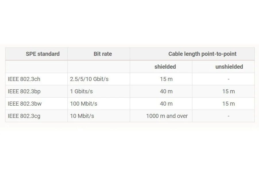
SPE is touted to be one of the next big communication standards in the industrial IoT segment. It’s been around for some time now but is starting to gain some traction. SPE is made with the single goal of reducing the physical size of the usual ethernet cables and providing similar data rates as the normal ethernet connection.
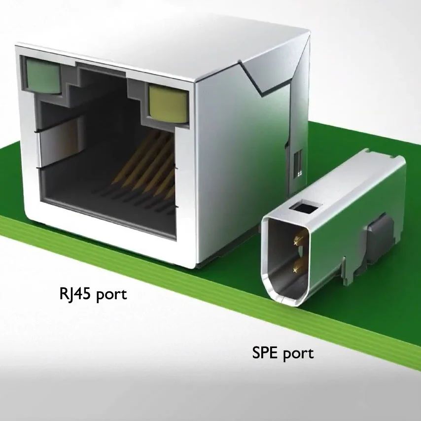
Fundamentally, SPE is just a pair of copper wires wound in a twisted pair format. Normal ethernet uses anywhere from 2-4pairs of wires to communicate with an ever-common RJ45(The one you commonly find on your WiFi routers) connector at its end. SPE can do speeds of up to 1Gbps between nodes if the distance is around 15m and the distance can be increased to 1km with a speed drop of up to 10Mbps. Another beautiful aspect of SPE is that it can deliver power also upto 50W of power (max current 1.36A to keep individual cables thin enough) on the data lines. It’s called Power over Data Line(PoDL) and is not the same as POE(Power over Ethernet). The form factor for this connector is also now standardised by IEC 63171-6 which makes it easier for interoperability. SPE connectors are much smaller in size(80% smaller compared with RJ45) and can come with IP20(solid object ingress) and IP67(waterproof) protections too.
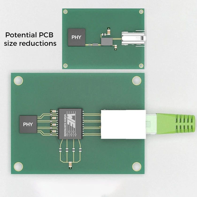
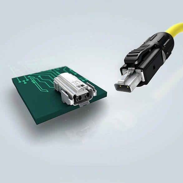
All of these make it perfect for industrial applications in terms of size and reliability. One place where I expect these to be integrated would be industrial machine vision cameras because of fast data rates and small connector sizes.

Suggested Reading: ANP085b white paper from Wruth.
If you liked the post, Share it with your friends!

Back to Basics: Crystals and Damping Resistors

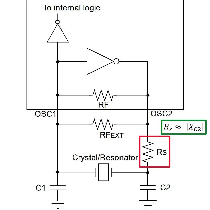
Continuing from the last post, one key element that one of my readers pointed out was the addition of an extra resistor at the output of the Pierce oscillator driver circuit in a uC. It’s a damping resistor and this is something which is not explained in a few newer datasheets and is usually ignored.

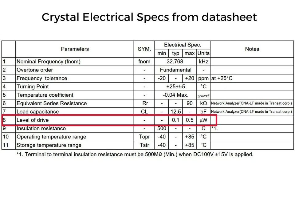
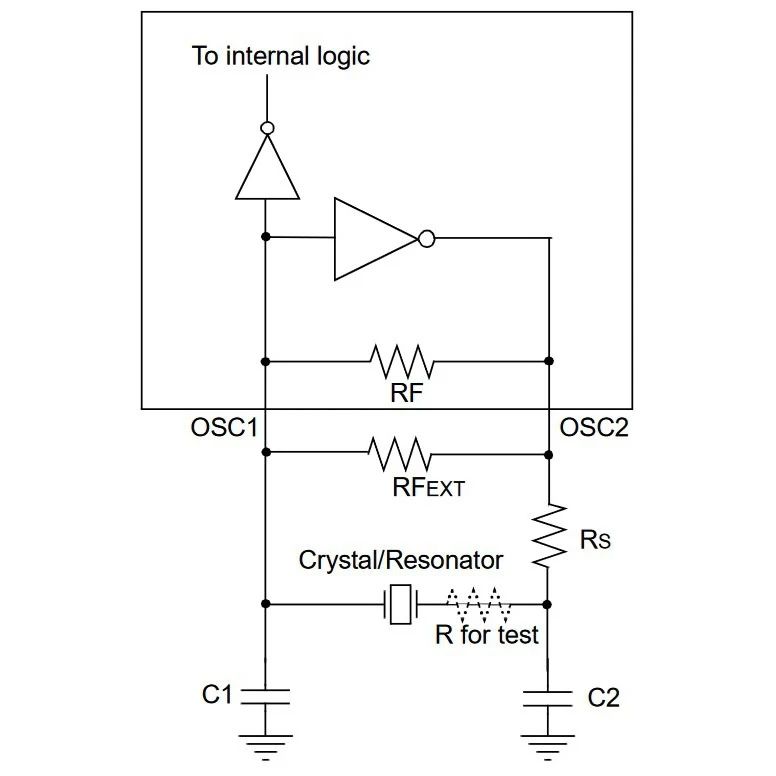
A damping resistor is needed primarily to adjust the Drive power of a crystal. Every good crystal manufacturer would add the maximum drive level in its datasheet. This is the maximum power(usually in microwatts) at which the crystal can be driven without damaging it permanently. To measure the driven level, you need to measure the current waveform to a crystal but Measuring this is a hard thing to do in the circuit. One method is to connect another know test resistance and measure the voltage difference with a differential probe to measure current. After the current is measured, test resistance is shorted out from the circuit. This is useful in SMD parts with no space. Another way is to measure it with a current probe in one of the traces. It’s expensive and hard to do on SMD parts so it’s preferred for thru-hole crystals with a probe connected around one of the legs of the crystal.

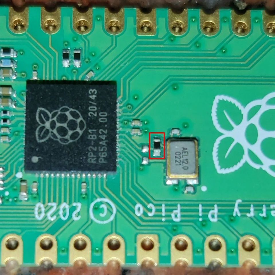
Once the RMS current to the crystal is measured, power is the squared multiplication of this current and the ESR(mentioned in the crystal’s datasheet). This power should not exceed the max value mentioned. If it does, you can try reducing the drive voltage from the uC(By adjusting the gain of the oscillator) or you add a resistor in series. The usual starting value of this damping resistor is equal to the impedance of external load capacitance(at the crystal freq) as mentioned in the figure. Using a normal voltage divider, you will see the drive will be reduced by half. Keep in mind that adding the resistor can add any additional phase shift to the oscillator circuit so you would want to double-check the crystal frequency once again in the circuit. For digital uCs these days, drive values from the Xout pin are set very low and hence you don’t see them in most datasheets.

If you liked the post, Share it with your friends!
1 25 26 27 28 29 58