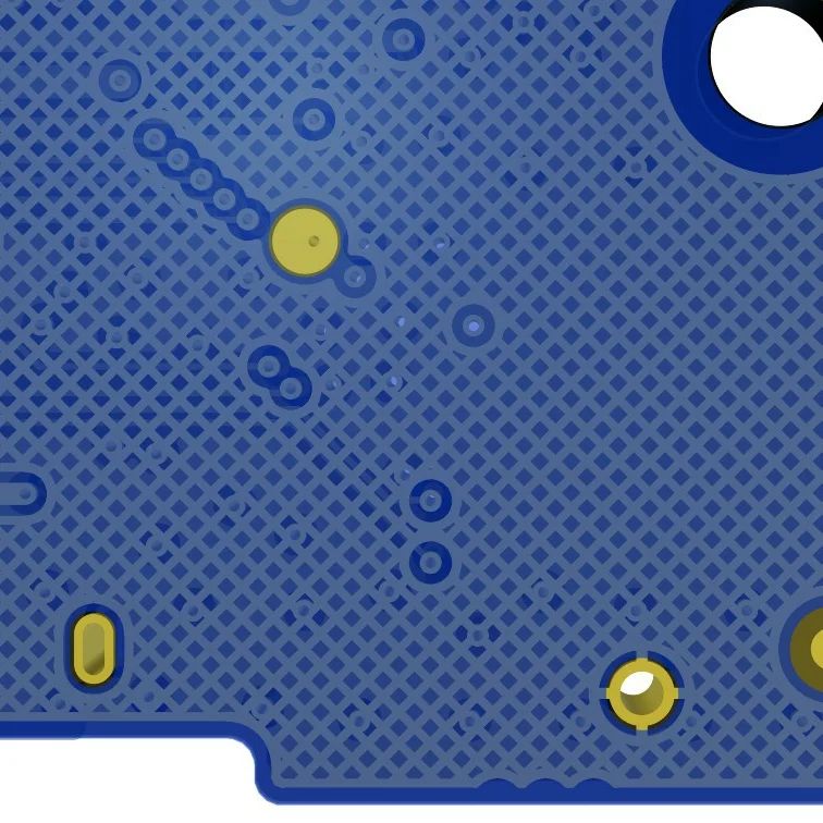
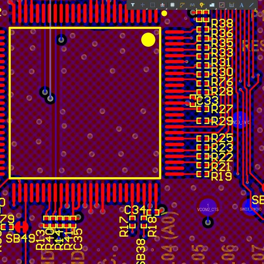
KiCad v6 Launch

It’s been almost 3 years since I started using KiCad for personal and professional workflows. I slowly tried to transition away from Eagle and Altium. In the initial days, KiCad had a huge learning curve coming from other CAD tools. Getting used to the interface and workflows were really painful. Once you have gotten used to its unique quirks, it all will start to make sense. These days I mostly use KiCad for most of my development activities(Except for legacy or specific client software mandated projects).

For those of you who don’t know, KiCad is a free and Open-source software to help you with Circuit schematic design and PCB Layout. It’s rare to find great free, open-source, feature-rich CAD tools out there. KiCad for me is up there with probably Blender. If you don’t want to pay the massive licensing fee of Altium or to be under the mismanagement of Eagle software by Autodesk, KiCad is definitely a viable option.

A couple of weeks back, KiCad v6 was launched. This for me is the biggest KiCad release to date in terms of features and based on the number of users who will migrate to this version. They made a lot of things simpler, based on user feedback. This is definitely going to reduce its barrier of entry. The UI got a refresh comparable to modern software. My favourite PCB-related change is the rounded corners on PCB tracks. Most of us are used the 45-degree bend for the change of direction of a PCB trace, rounding it makes it look even better(Lesser impedance discontinuity for very high freq signals). For anyone thinking of doing a jump to KiCad for their workflow, I would say version 6 is probably the best one to learn it from scratch. It’s so much better.

PS: KiCad is going to be a CAD tool in your arsenal like any other. A CAD tool is only as good as how you can use it. It doesn’t matter which tool you use as long as you can use it well and solve your problems with it. It’s always a personal choice and don’t let anyone tell you otherwise(It will just lead to fanboy software flame wars).

KICAD
KICAD
KICAD
If you liked the post, Share it with your friends!

Casio MJ1200 Calculator Teardown

Pocket calculators are a classic example of something which has been around since the 1970s and has undergone optimised design over the years. These still do have a place in the world despite the touch-based software phone calculators out there. The tactile button press feedback is something that a heavy user will always appreciate.

Casio Calculator Teardown

The basic building blocks of a calculator will be your power source, a matrix keypad, an array of 7 segment LCDs and an ASIC(on a black blob) built for cost. The matrix keypad will be a standard row-column arrangement with multiplexing being used to read out the button presses. The button would consist of a carbon-coated unit with a zig-zag portion on the PCB which will effectively make a short with carbon when pressed. The 7 segment LCDs are monochrome and mostly reflective based. Since most calculators don’t carry a backlight they are quite low power to drive(One of the reasons why calculator batteries seem to last forever). The LCD segment is connected by a ribbon cable which is usually glued in place in a PCB(Not soldered) with carbon tracks. If you ever see certain segments in a calculator not lighting up, try heating the cable connector on the PCB end, it should mostly work.

The power section of these calculators usually contains an alkaline button cell battery(1.5V, Not rechargeable). Most of the calculators come with a solar cell array to act as a dual power source. This one had 4 solar cells with a total open voltage of approx 2.5V. It uses the classic power OR-ing circuit. Both battery and solar cells feed into the same PCB track with individual Schottky diodes(Parallel). So solar does contribute to the longevity of the calculator’s battery life. The Schottky diodes in the circuit prevent the reverse charging of the battery and have a low dropout of approx 0.15V. It’s the cheapest possible arrangement based on BOM costing for powering the device. That 0.15V drop is OK for low power circuits like these but won’t scale for larger circuits and hence most IC companies make a killing with power path management ICs these days (Well that’s a discussion for another day entirely)

If you liked the post, Share it with your friends!
1 70 71 72 73 74 86