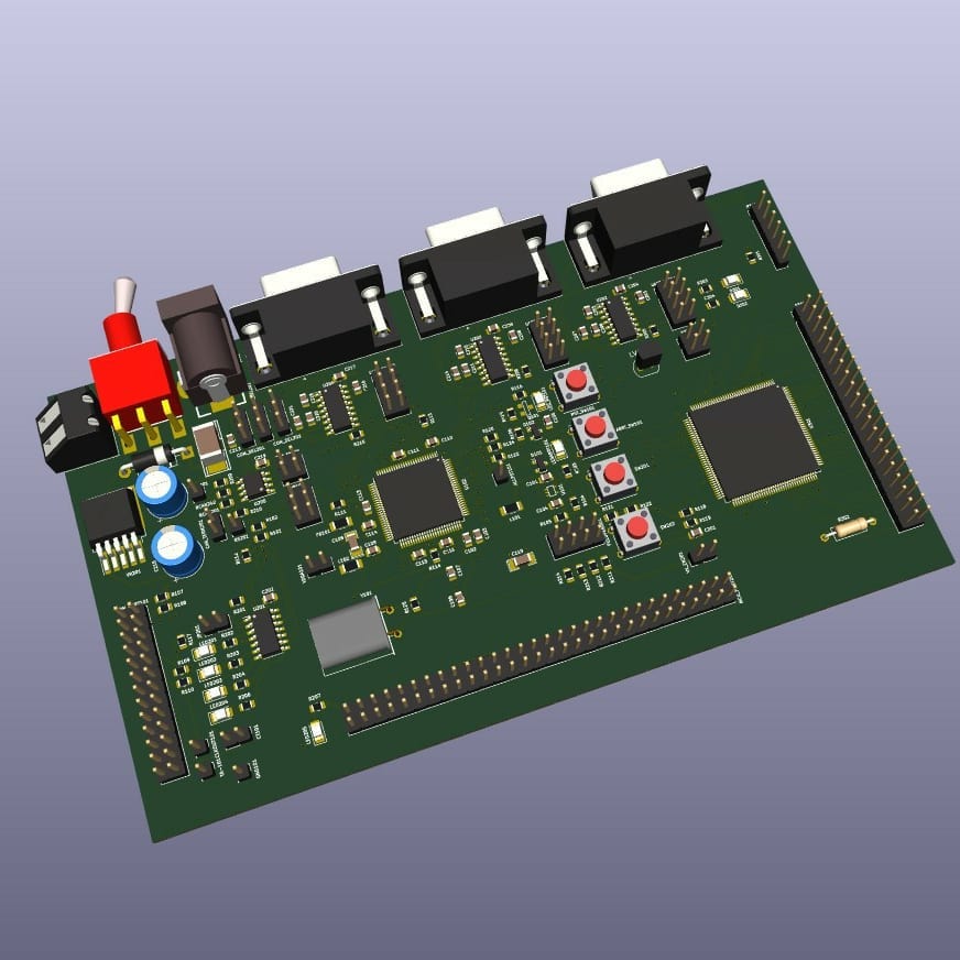
It’s been almost 3 years since I started using KiCad for personal and professional workflows. I slowly tried to transition away from Eagle and Altium. In the initial days, KiCad had a huge learning curve coming from other CAD tools. Getting used to the interface and workflows were really painful. Once you have gotten used to its unique quirks, it all will start to make sense. These days I mostly use KiCad for most of my development activities(Except for legacy or specific client software mandated projects).
For those of you who don’t know, KiCad is a free and Open-source software to help you with Circuit schematic design and PCB Layout. It’s rare to find great free, open-source, feature-rich CAD tools out there. KiCad for me is up there with probably Blender. If you don’t want to pay the massive licensing fee of Altium or to be under the mismanagement of Eagle software by Autodesk, KiCad is definitely a viable option.
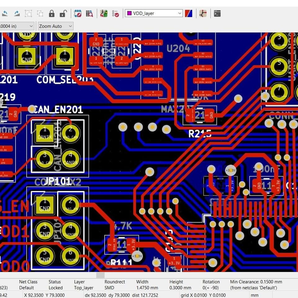
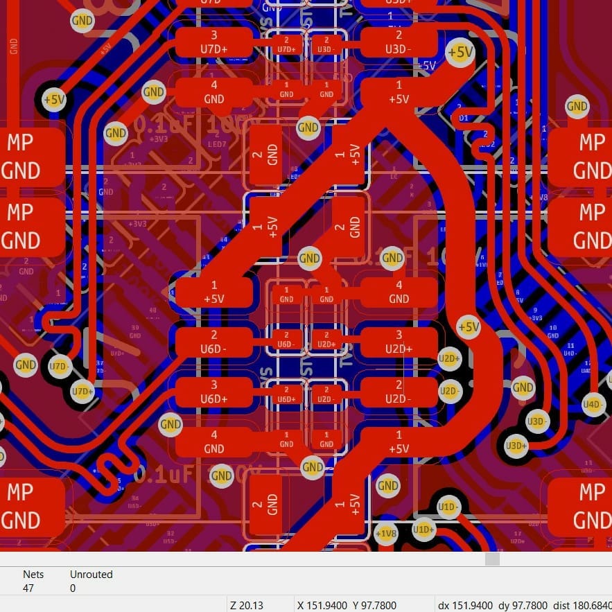
A couple of weeks back, KiCad v6 was launched. This for me is the biggest KiCad release to date in terms of features and based on the number of users who will migrate to this version. They made a lot of things simpler, based on user feedback. This is definitely going to reduce its barrier of entry. The UI got a refresh comparable to modern software. My favourite PCB-related change is the rounded corners on PCB tracks. Most of us are used the 45-degree bend for the change of direction of a PCB trace, rounding it makes it look even better(Lesser impedance discontinuity for very high freq signals). For anyone thinking of doing a jump to KiCad for their workflow, I would say version 6 is probably the best one to learn it from scratch. It’s so much better.
PS: KiCad is going to be a CAD tool in your arsenal like any other. A CAD tool is only as good as how you can use it. It doesn’t matter which tool you use as long as you can use it well and solve your problems with it. It’s always a personal choice and don’t let anyone tell you otherwise(It will just lead to fanboy software flame wars).