Back to Basics: LEDs Part 2: Series Drivers

LED Series Drives

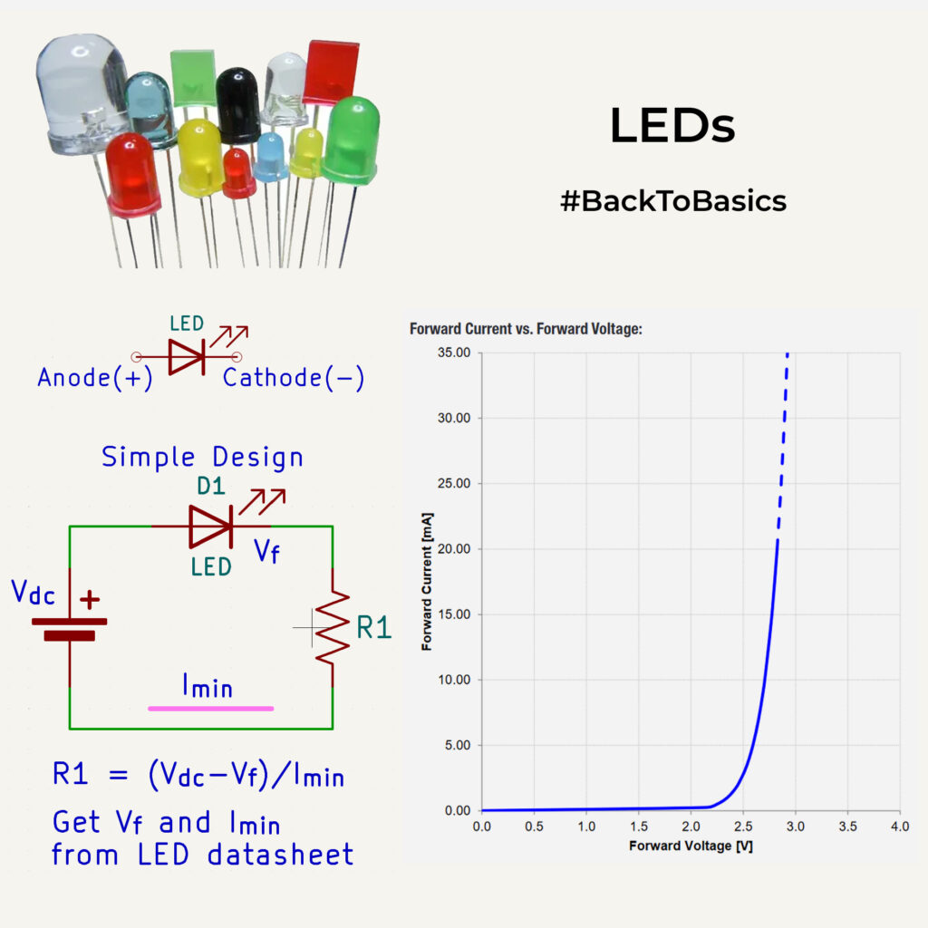
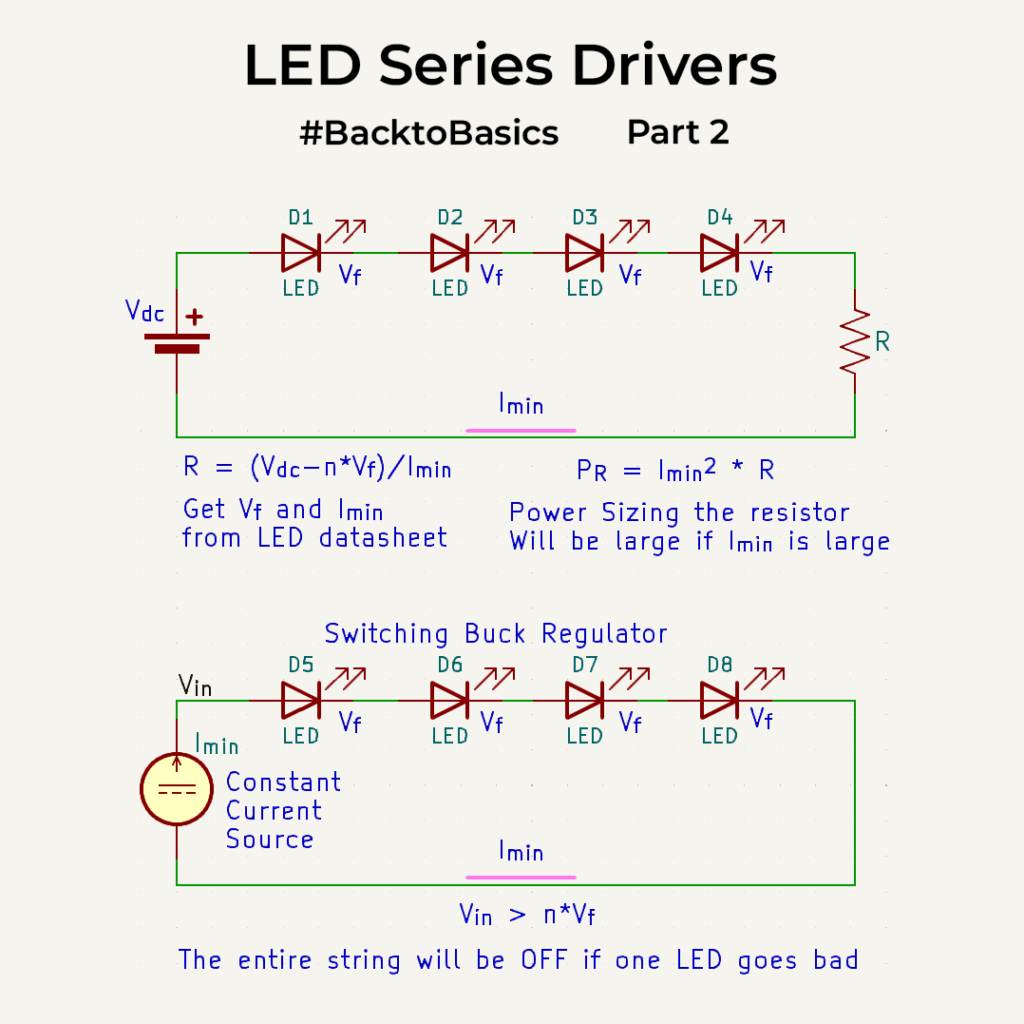
We started off with what it takes to drive a single LED. Now the easiest way to drive multiple LEDs is to connect all the LEDs in Series and limit the current in through them via a normal resistor. If you drive it with a large enough voltage. It works, but is inefficient. Once you find the resistor value, the key thing will be to figure out its size for power dissipation calculation. For high current LEDs and with nominal resistors, Power-dropped is related to the square of the current and power rating needed increases drastically. Well this power is dissipated as heat on the resistor and is not something we want if we need in energy efficient systems.

So to fix this we use a constant current source which drives the LEDs with a constant current. Current is usually fixed by setting a resistor which will be referenced to a smaller voltage so no need to worry about the sizing of that one. This is probably the most common mode of driving LEDs out there. But there is a problem here, the drive voltage output of the string of LEDs should always be higher than the sum of Vf’s as the most common topology will be a buck mode. ie) If your input power supply is say a USB of 5V, then you can probably drive only a couple of LEDs in series(that too if it’s not white as they have a Vf of 3V+). if you have a lot of LEDs to be lit up, then this is not a right topology for you. For that you now need boost mode topology or parallel drive, which is a whole topic in itself. Boost topology will increase the output voltage relative to the input but only to a certain point. One point of consideration is frequency of switching of your buck/boost regulator. We will get into the why of that later on in this series. Also, the major issue with series drives is if one of the LEDs blows up, the entire string stops working.

If you liked the post, Share it with your friends!

Back to Basics: LEDs: Part 1

LED Basics

I thought I should probably do a series on the ubiquitous LEDs in electronics design. You might be thinking what’s there to learn about that? TBH there are a lot more things than you think. Most times when I start embedded hardware interviews, I start with basic LED circuits and how to use them in circuits. Lots of fundamentals to probe there. Surprisingly, even seasoned experts trip up on this area.

At the heart of every LED is a semiconductor chip composed of layers of materials, typically gallium arsenide/phosphide/nitride. When a voltage is applied across these layers, it excites electrons, causing them to jump from the conduction band to the valence band. As they return to their stable state, they release energy in the form of photons, creating visible light. It’s called electroluminescence.

Every LED has forward voltage(Vf) and it changes with color. Everyone knows the exponential IV curve from your first electronics class. LEDs don’t pass current till Vf is reached and then increases drastically. Approx Vf values for diff colours are as follows

Red-1.8- 2.2V

Green/Yellow- 2 – 2.2V

Blue/White- 3 – 3.4V

What you also need to remember is Vf changes(by upto even 20%) even between the same type of LEDs, from the same manufacturer, even from the same batch. Because of this, LEDs are driven with a constant current rather than a constant voltage. Usually more current, more light an LED produces till a point. A very basic LED drive design is there in the pics. It’s our job as circuit designers to ensure what’s the minimum current that needs to pass, to produce the required light output. We will see all about that and more in the upcoming posts.

Feel free to follow or share with a colleague if you believe this series could be valuable, or simply as a helpful refresher.

If you liked the post, Share it with your friends!
1 51 52 53 54 55 118