Although not fully related to oscilloscope probes per se, I thought it was important to cover the aspect of AC/DC input coupling in scopes. It’s one of those things folks working with an oscilloscope for the first time randomly try to switch between the modes to see if the waveform comes properly. AC and DC coupling are two settings that determine how the input signal is coupled or connected to measurement circuitry.
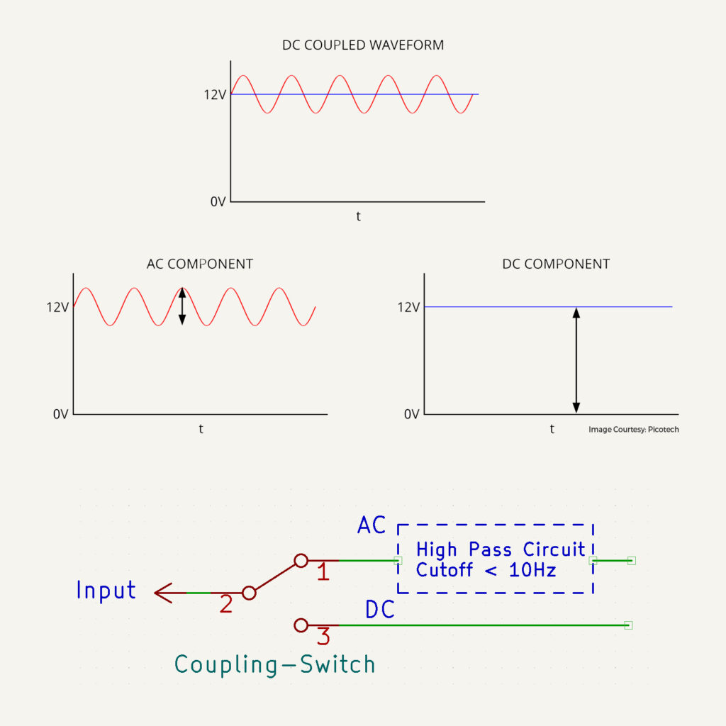
DC coupling allows the oscilloscope to display both the AC and DC components of the input signal. Meaning if there is a DC shift in the AC signal it will also be shown. Let’s take an example, let’s say you want to measure the AC ripple/noise in a 24V DC power supply. If you connect the probes to the output of a supply and switch to DC coupling it will show the 24V signal + Ripple. But since the vertical screen resolution on a scope is small, you have probably put the voltage division set to 5V/div. Now you just see a flat DC at 24V towards the top, but the amplitude resolution of the ripple is lost as it might be in the range of say 300mV Vpp. Displaying this 300mV AC waveform on a large voltage division setting won’t give you any resolution and hence you can’t see the waveform.
This is where AC coupling helps. Switching to this mode, all it does is block the incoming DC signal(24V here)and you are left with only the ripple waveform, now you can switch to a voltage knob setting of say 100mV/div to clearly see 300mV Vpp waveform for further analysis. How do they implement this? In its basic form, all it is is a switch that puts a high pass filter with a cutoff ranging from 3Hz-10Hz(diff vendors) in the path of the incoming signal which blocks the DC. So here in lies a problem, only switch to the AC mode if you know that measurement freq is high or to block DC. For example, when measuring a 10Hz AC signal in AC coupling mode, the amp of measurement will be wrong as the high pass filter’s roll-off range will not be that sharp for lower freq ranges. So, switch to DC mode in these cases.
Remember the purpose of each mode and choose accordingly. A helpful way to remember is
DC Mode: Think “Direct Coupled/Connection” (Signal un-affected)
AC Mode: Think Only “AC-Coupled” through