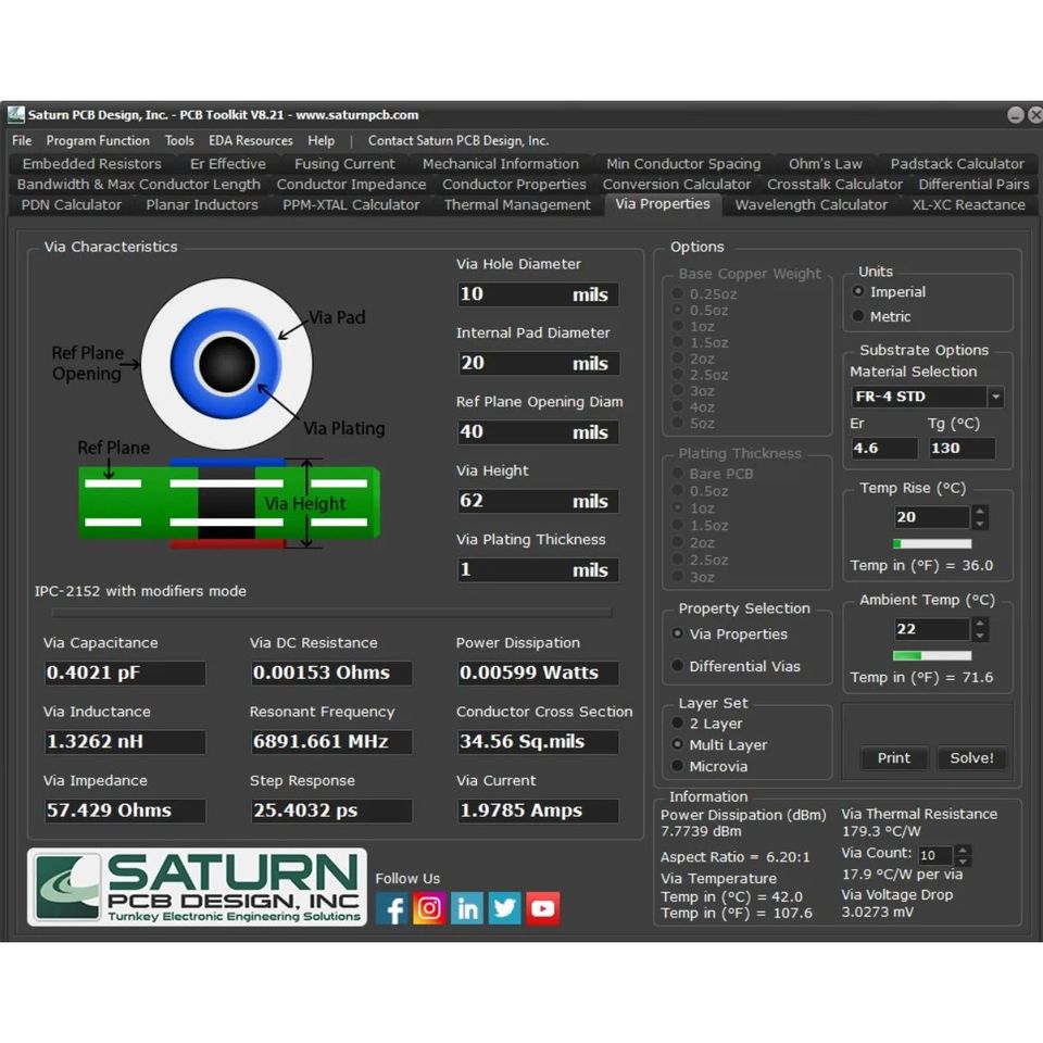
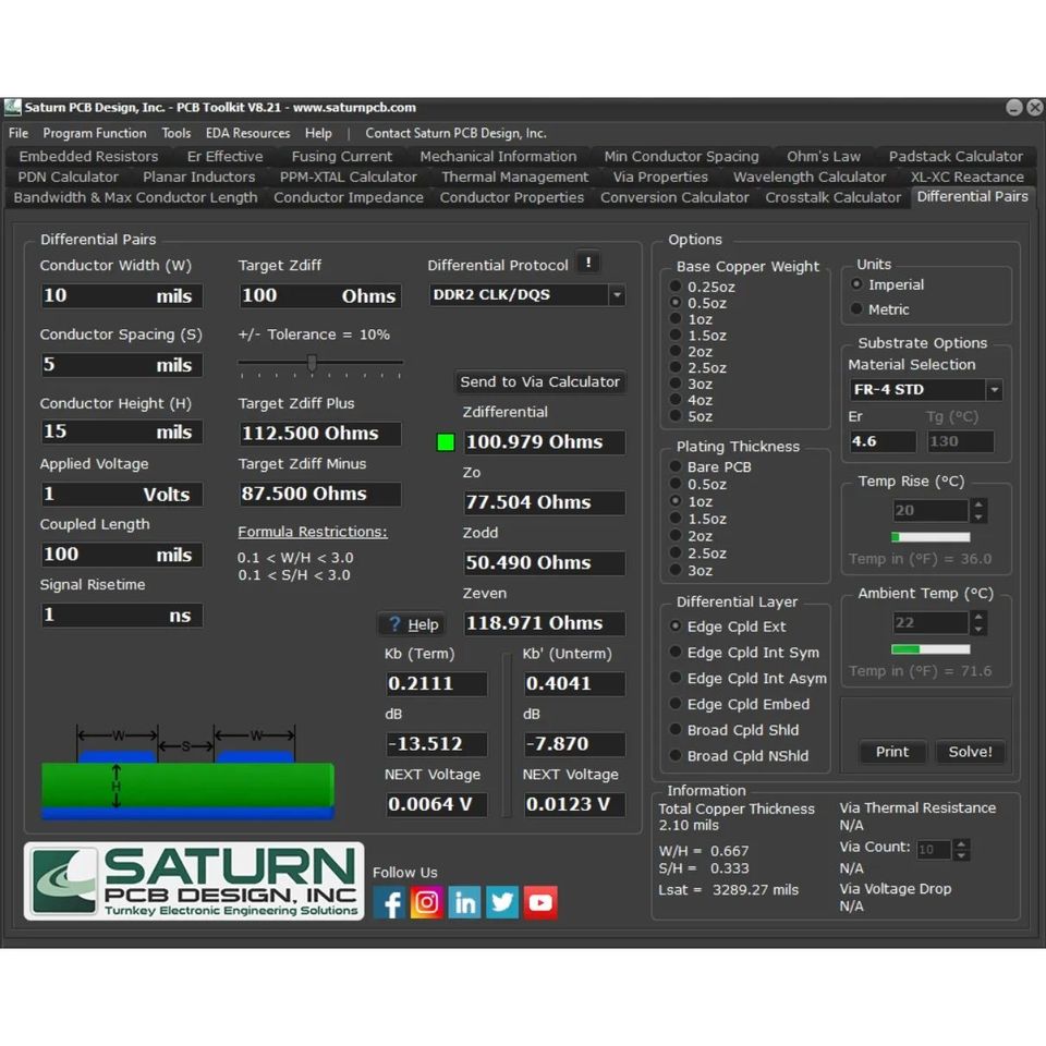
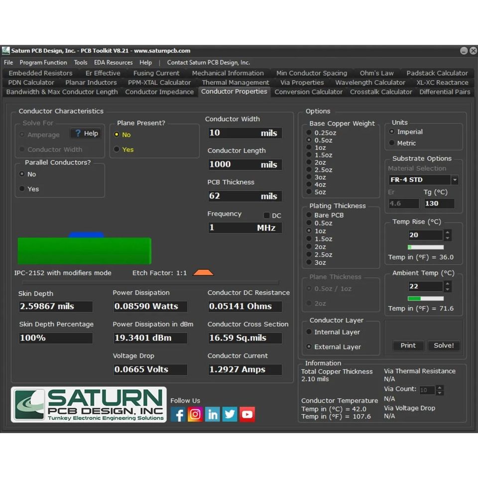
While designing PCBs there are a lot of parameters one needs to account for. That’s where standalone calculators(and some online ones) really shine. One of the best ones out there in the freeware domain is PCB Toolkit by SaturnPCB. I have been using this for years now. It’s a stunning bit of software which contains so many calculators rolled into one. You have an impedance calculator for figuring out the width of trace in PCB for the desired impedance profile, you have a differential pair calculator to fine-tune your target impedances for differential high-speed traces. Via & Current rating calculators to size out your current tracks based on thermal and current carrying capabilities. Beyond that, they have lots of smaller measurements which makes it a one-stop option rather than Googling each time. Try it out, there are too many to explain in detail.
How accurate are these calculators? There are usually able to give you a near good enough value as it’s mostly coded up based on equations. You will see definitely slight variations in real life. It won’t probably give the accuracy of very expensive simulators out there but it’s good enough.
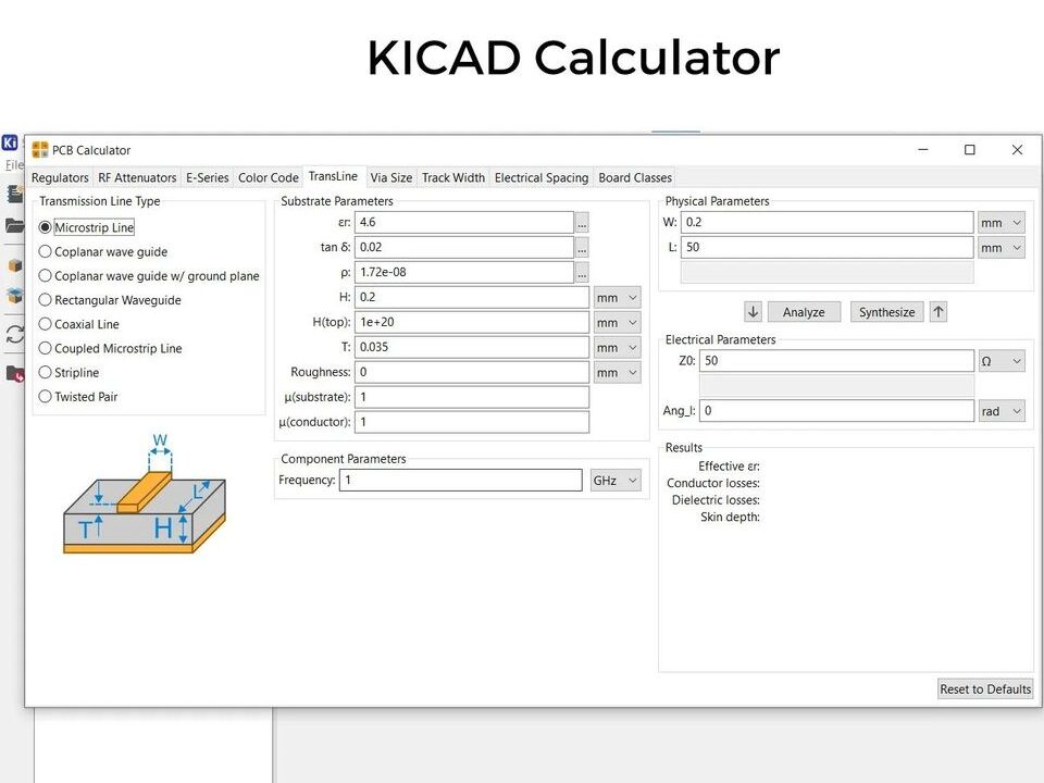
BTW KICAD PCB software also has a few built-in PCB calculators, it’s not that extensive though.
Would love to hear about any other PCB/EE calculators that you use in your workflow.