Back to Basics: ESD Capacitance

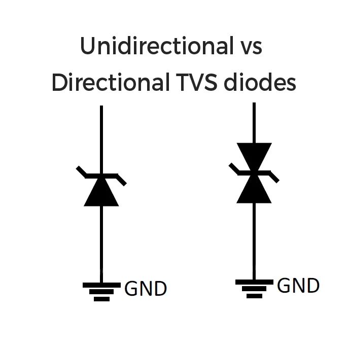
Last week we focussed on one facet of ESD diode selection which was unilateral vs bilateral and focussed on when to use each one of them. Another critical item to discuss is ESD capacitance. Please don’t confuse ESD Capacitance with an “ESD capacitor” which is an entirely different thing.

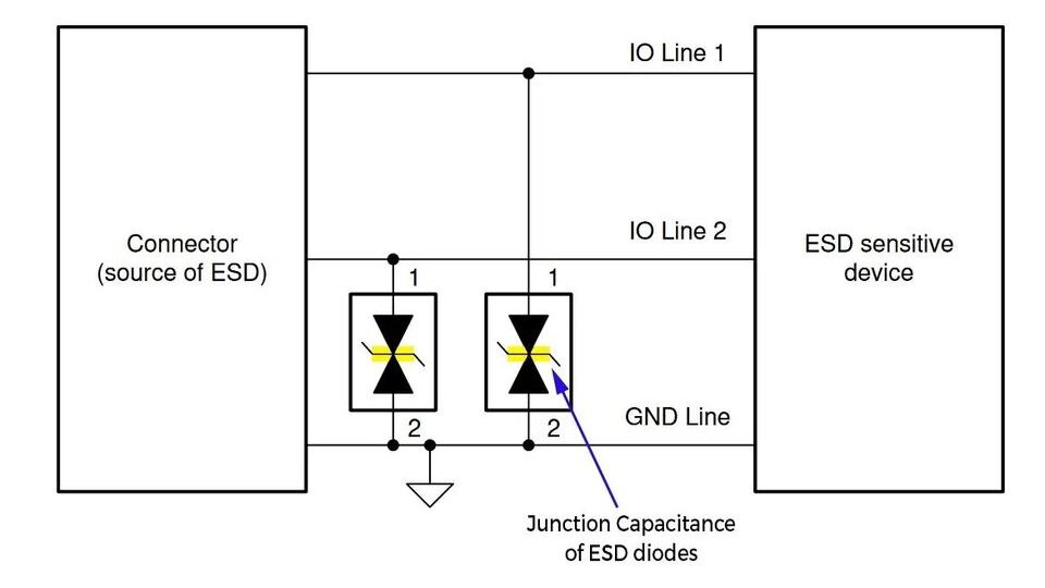
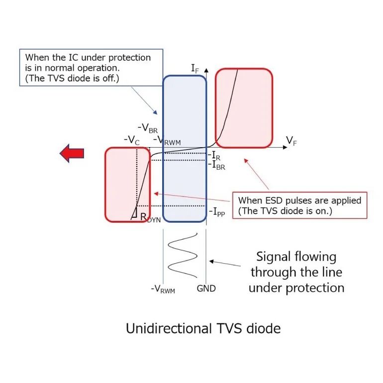
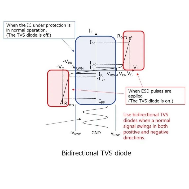
Every ESD diode is connected in parallel to a line/trace that it tries to protect from ESD strikes. ESD strikes are usually rare and in the normal operation of the device, ESD diodes ideally should not affect the regular functioning of the circuit. This is where the capacitance of the ESD diode matters. In normal operation, the ESD diode in the reverse biased mode, shows a capacitance due to its PN junction. The value of the capacitance has a huge role to play in the lines it protects. If you use a diode with higher capacitance to protect lets a high-speed signal like USB 3.2 Super Speed TX/RX data lanes it will create a problem. These data rates are in 10+Gbps and this pulls the line low and high at a very fast rate. Adding a larger capacitor diode will reduce its rise and fall times which will cause communication errors and you make fail the USB compliance eye diagrams.

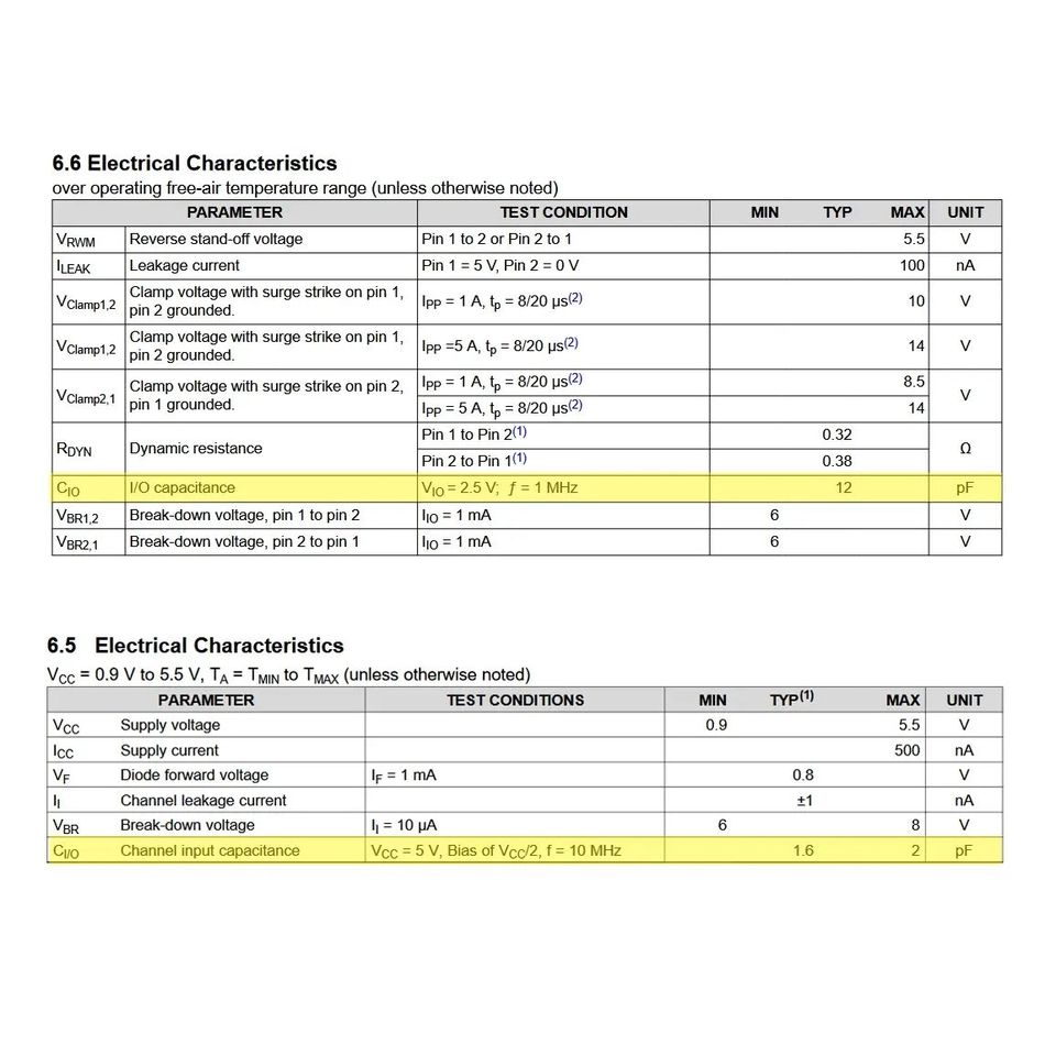
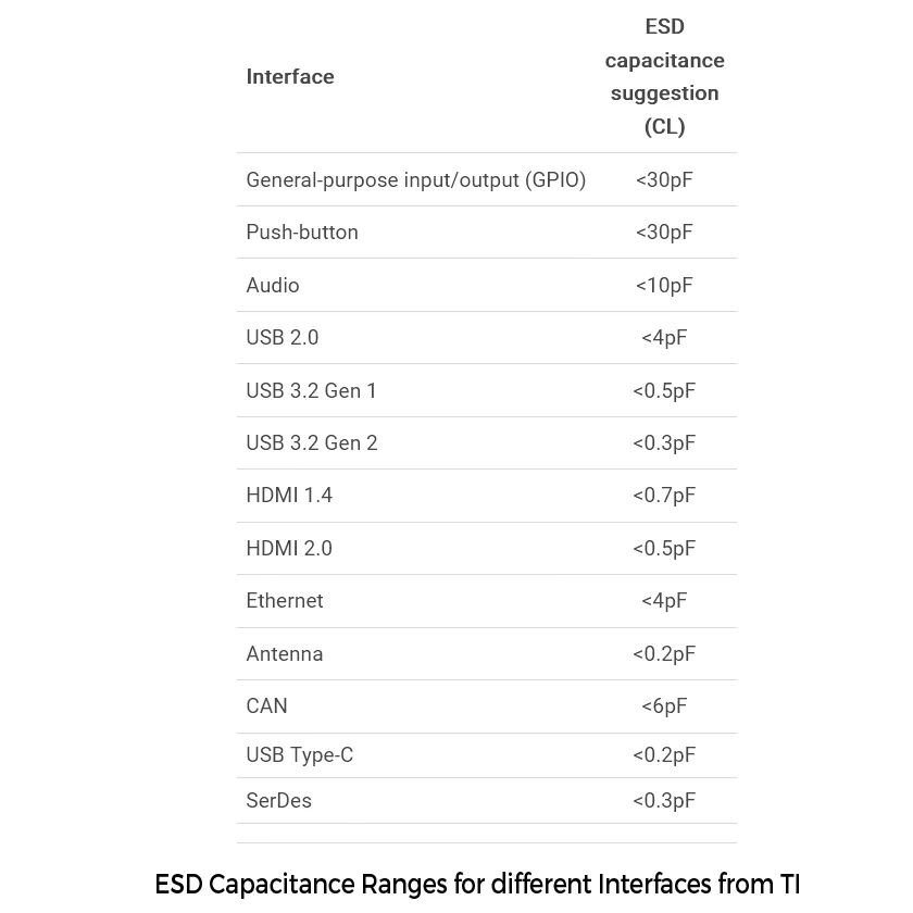
Hence when you select an ESD diode make sure to use low-capacitance ones for high-speed data lines. You can use higher capacitance ones for GPIO/Vbus lines as there are slightly cheaper if needed. TI has a good chart(check images) on the website showing you the different capacitance ranges and which you can use for different applications based on speed.

If you liked the post, Share it with your friends!

Back to Basics: ESD diodes – Unidirectional vs Bidirectional

I thought should do a few posts in general and advanced about Electro Static Discharge(ESD). There are a lot of small things which can trip up anyone doing circuit designing for the first time. Firstly, ESD protection at the input is something you should do when designing a product which is meant to be sold anywhere. One is because ESD can definitely ruin your devices and secondly because standards mandate that you provide protection for it.

You provide ESD protection to places where someone can actually touch your device. This is mostly at the input side like cable connectors, and power inputs. When a human body is charged up, it can deliver voltages in the Kilovolt range for a short duration. For those of you who didn’t know, it’s the same shock that you get when you touch a metallic doorknob after walking around on a carpet. This high voltage is more than enough to fry the circuits you can physically touch. So it’s imperative that you protect the circuits from ESD.

The usual method to do it is via TVS diodes. These are diodes which are placed at the input to protect against ESD. In order to simulate ESD events in a test lab, we have a standard called IEC 61000-4-2 which defines the test procedures and various voltage levels of protection. The device under test is applied with contact voltages of up to ±8KV for a tiny interval of time for a Level 4 rating(I will get into the specific test some other day if there is interest). The device should ideally be able to survive this ESD strike. As you see, both positive and negative ESD pulses are given to a circuit as you can be positively or negatively charged in real life.

Now, what are unidirectional and bidirectional TVS diodes? These are diodes which are designed to break down and maintain a voltage when it exceeds a predefined level. This helps it save the circuit downstream from damage. They are connected in parallel to your inputs. Here is where a common confusion occurs, should I be using unidirectional or bidirectional TVS diodes for protection? A wrong way to think of it is, “Because my ESD tests can be in the positive and negative regions, I need to use a bidirectional one for protection”. That is simply not true. If you see the VI chart comparison of the diodes you will clearly see the difference between the two. A unidirectional diode clamps the voltage level in one direction after a threshold but in the other direction, it breaks down immediately. Whereas a bidirectional one has these threshold limits on both sides. Why is this useful? Suppose your normal accepted input voltage can go negative with respect to ground-like audio signals or ±5V . If you don’t use bidirectional ones, it will simply clip the negative range and you lose the signal. Hence choose a diode based on what sort of input voltages you are expecting. Unidirectional ones are cheaper and widely used as most input signals are positive wrt the ground.

If you liked the post, Share it with your friends!
1 23 24 25 26 27 58