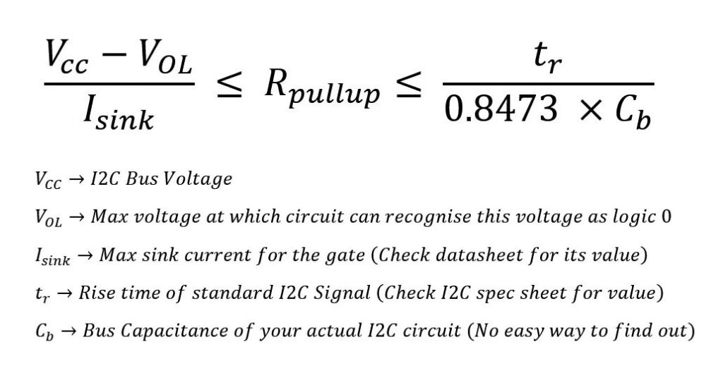
Since there was a large interest from quite a few folks regarding the last post, thought of continuing that design series on how to select pull-up resistors for I2C. (Check images for the formulas)The lower limit of the resistor is defined by V_OL which is the maximum voltage that can be recognised as zero by your circuit. Eg. If 0.4V and below is taken as zero in the digital circuit, V_OL = 0.4V. The sink current is the current which can be taken by your gate. You can find this in your sensor’s/microcontrollers datasheet in the electrical specs section. These two values determine the minimum value needed for your I2C bus to function.
On the upper end, it’s decided by the rise time mentioned in the standard I2C spec and the bus capacitance. Rise time values(in ns) from the I2C spec sheet for different speed modes of I2C are as follows
– Standard-mode (Sm, 100Kbps) –> 1000ns
– Fast-mode (Fm, 400Kbps) –> 300ns
– Fast-mode Plus (Fm+, 1Mbps) –> 120ns
– High-speed mode (Hs-mode, 3.4Mbps) –> 80ns
So pick a value from the above list based on the speed of operation of your I2C system.
Bus capacitance is the effective capacitance shown by your I2C bus. This is specific to your PCB/breadboard implementation and will vary based on your design. The ideal goal is to have as small a capacitance as possible so that you can transfer data faster. Larger capacitance means that it takes more time for the signal to reach its logic high(larger rise times) and sometimes it might never get to logic high causing problems in the communication. The capacitance of your bus will always be higher if you have longer bus lengths, PCB-to-wire connections, and more devices connected on the bus.
There is no simple way that I know of to calculate bus capacitance in the design stage. The practical way is to build out your circuit by calculating the pullup resistor(above the lower limit) and sending I2C data on the bus. Now probe the SDA and SCL line with a scope and measure the rise time. Now using the RC time constant formula back-calculate the bus capacitance for your circuit. Now with this, you can modify your pullup resistance formula if needed. If capacitance/rise times are not problematic in your circuit always go with the highest value of resistance possible so as to minimize power loss. I2C is a power guzzler.
PS: Refer TI’s SLVA689 whitepaper to see derivation on how you got the formulas mentioned for pullup resistor designs