Tech Explained: AC cooling

It’s summertime in India and most of you must be sweating through the day. Those of you who can afford air conditioning at home are probably running it at full blast now. I recently learned that AC tech does more than just cool the air. Since this knowledge isn’t common, let’s discuss it in detail today.

A residential AC is a heat pump. In a humid place, your AC also functions as a water-removal machine. Fundamentally it does not create cold air. It moves heat from your room to the outside. A refrigerant(fluid that easily changes between liquid and gas) absorbs heat at the indoor coil. The compressor squeezes it, and the outdoor coil throws that heat outside. In humid air, the indoor coil has a second job. When warm moist air touches the cold coil, air temperature drops. If the coil is colder than the dew point (the temperature where air can no longer hold all its moisture), water vapour turns into liquid water and drains out.
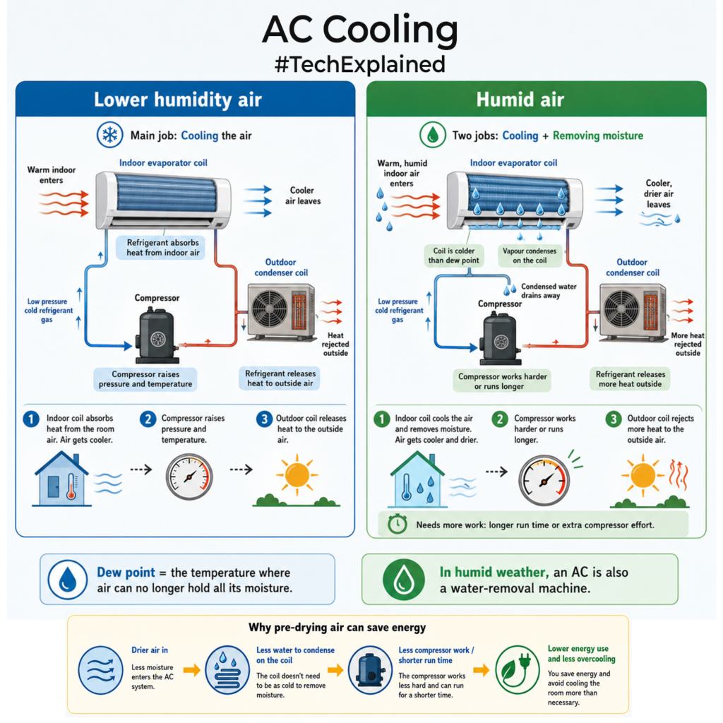
This is where humid climates are hard on ACs. If the room only needs a small temperature drop but the air is wet, the system still has to make the coil cold enough to condense water. That means longer run time, lower coil temperature and more compressor work. Removing water is not free because changing vapour into liquid takes energy. You are forcing water to change phase. This moisture removal can be more than 30% of the AC load.

That is why new cooling solutions are not only about better compressors. I was reading about the Global Cooling Prize and a few approaches from companies working on this problem. There is a company called Transaera that uses advanced porous desiccants to pull moisture out before cooling. The idea is simple. If the incoming air is already drier, the AC does not have to waste as much energy forcing water out on a very cold coil. Another group Kraton, with IIT Bombay, explored a membrane that lets water vapour move out first, then uses evaporative cooling.

I am new to the domain but I think this is an important shift that newer AC tech is moving towards to heat removal and moisture removal(passively) at maybe lower power even.
If you liked the post, Share it with your friends!

Back to Basics: Auto Balancing Bridge Circuits

I was reading up for a client project on impedance measurements. While digging through, I ran into the auto-balancing bridge circuit used inside many LCR meters, and it’s worth understanding.

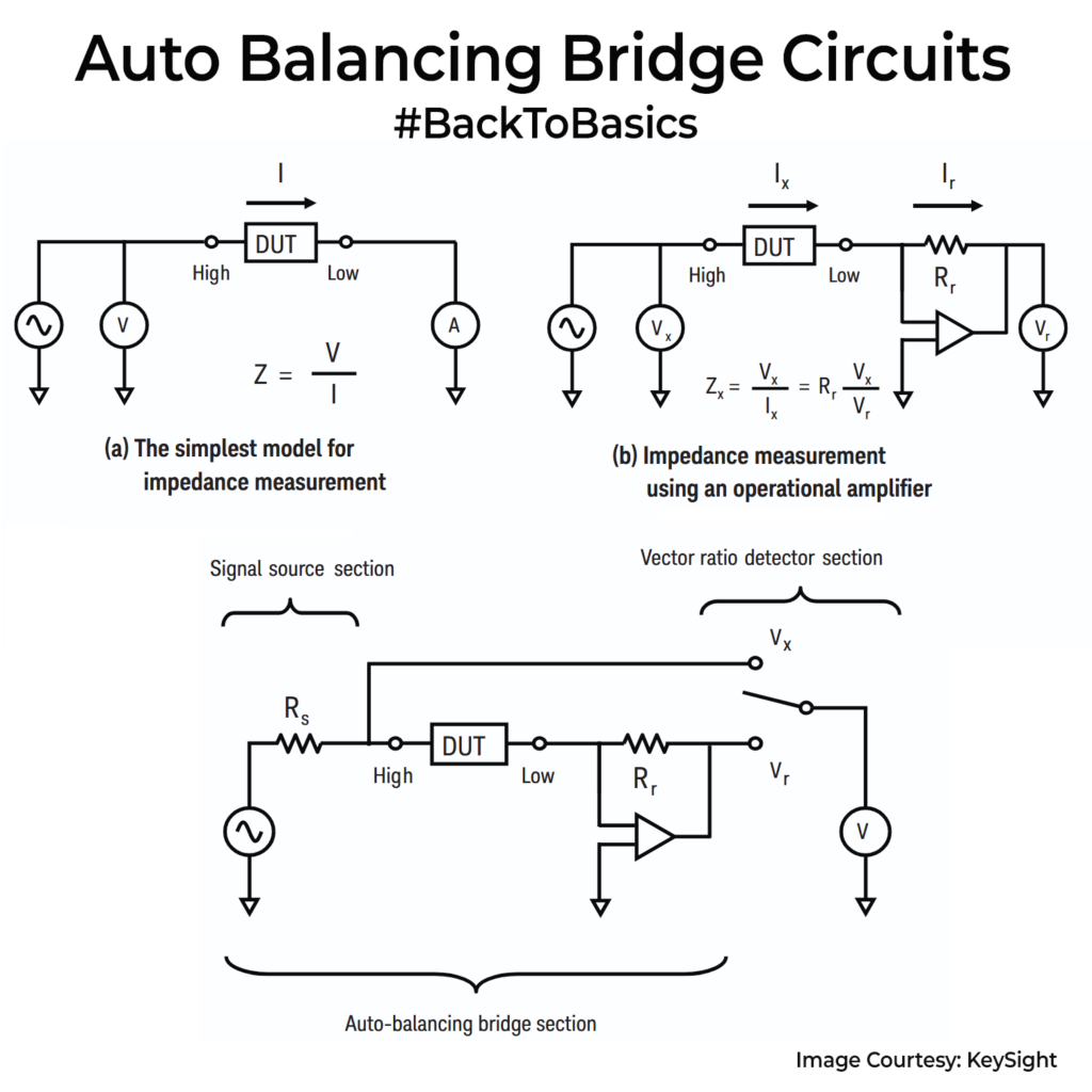
In the simplest form, impedance is just Z = V/I. You drive the DUT with a sine, measure the voltage across it, measure the current through it, and then divide. The problem is that an AC ammeter is never ideal. Its input impedance, wiring, and stray capacitance start affecting what you measure.

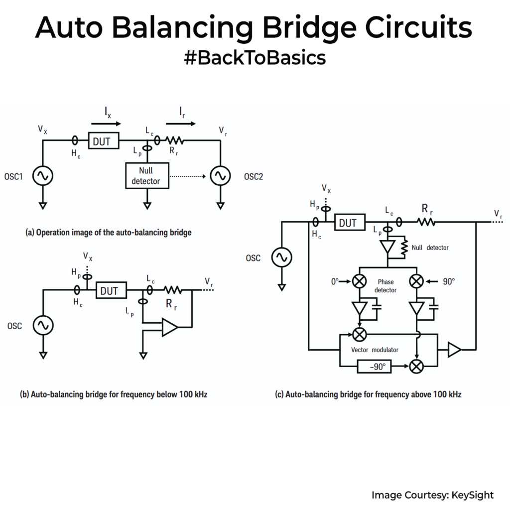
The auto-balancing bridge avoids measuring current directly. Check the images. Circuit forces the DUT current Ix to flow through a known range resistor Rr using a feedback amplifier. The Low terminal is driven to a virtual ground, close to 0V. Now the current becomes a voltage Vr across Rr, so Vr = Ix * Rr. You also measure Vx across the DUT. Put those together and you get Zx = Vx / Ix = Rr * (Vx / Vr). The instrument is really doing a vector ratio(Vx / Vr).

This setup would use two vector voltmeters, one for Vx and one for Vr, then take the ratio. The catch is there can be mismatch between meters. So many LCR meters instead switch one voltmeter receiver between Vx and Vr, so the same front end measures both and tracking error largely cancels.

Below about 100 kHz, an op-amp transimpedance stage can hold the Low node near 0V and convert Ix into Vr. Above that, bandwidth limits and parasitics make the balance drift. So instruments add a null detector that senses leftover error current, split it into 0° and 90° parts, and drive a vector modulator to tweak amplitude and phase until the error goes to zero. That closed-loop correction is the auto in auto-balancing. BTW, its called auto-balancing because the instrument doesn’t rely on you to manually “balance a bridge” like old Wheatstone-style bridges. It uses a feedback loop that continuously drives the error toward zero on its own.

You use this circuit for getting your impedance U curves for capacitors, ferrite beads etc to a particular freq limit. For very high freqs (GHz), you often switch to network analysis/VNA methods.

If you liked the post, Share it with your friends!
1 2 3 4 5 99