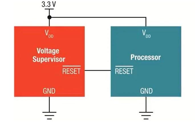
Voltage Supervisor ICs are ICs that monitor the voltage of a particular rail, (most of the time, the power supply rail) in a system. They are used to ensure that the voltage levels remain within the safe operating range and to provide a reset signal in case of an over/under-voltage event. They are especially used in microcontroller-based systems, where they monitor the voltage levels of the power supply to prevent the microcontroller from operating outside of its specification or the brownout region. If you check the datasheet of any microcontroller, you will find a lower threshold voltage, now if you feed a voltage lower than that, then the microcontroller may just stop. If it just stops working there is no problem, but most of the time, it goes into a limbo state wherein you can predict its behaviour, it starts misbehaving. This is one of the worst-case scenarios to debug as it’s random behaviour.
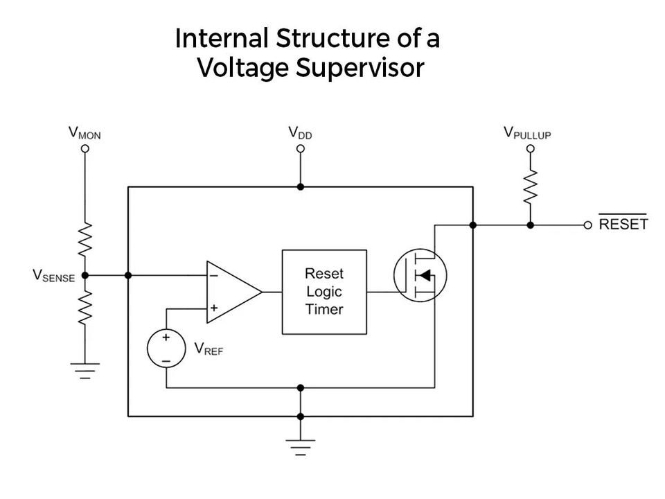
Voltage supervisor ICs play a crucial role in ensuring system stability. They monitor the voltage levels of a system and trigger a reset if they fall below normal limits. Essentially, they consist of a comparator with a voltage divider and a precision threshold voltage that compares the input voltage with the set limit. They can be used to trigger enable pins of LDOs, and buck converters also, not just uCs.
There are several types of voltage supervisor ICs, including fixed voltage ICs, variable threshold ICs with external resistors, and ICs with built-in watchdog timers. These ICs are essential for mission-critical systems, especially when they are battery-powered, as they prevent the system from malfunctioning due to low battery voltage. With a voltage supervisor IC in place, you can be confident that your system will perform optimally in all scenarios. Worth using if your BOM budget allows for it.