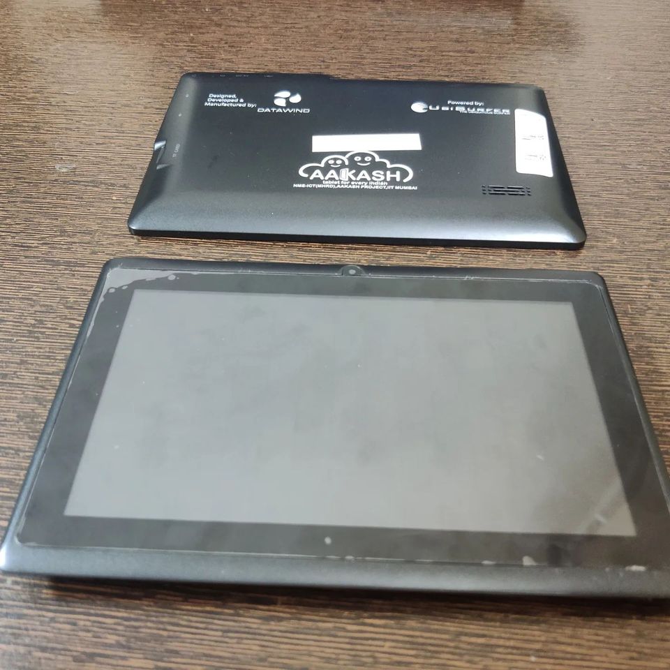
Found this old tablet lying around in our labs. It’s an old Akash tablet (2013 Model). It was designed and manufactured by the Indian company DataWind. It was a $50 tablet launched by the Indian Govt to provide low-cost tablets to students in order to increase access to educational resources and improve learning outcomes. IIT Bombay procured around 100k tablets for distribution across the country.
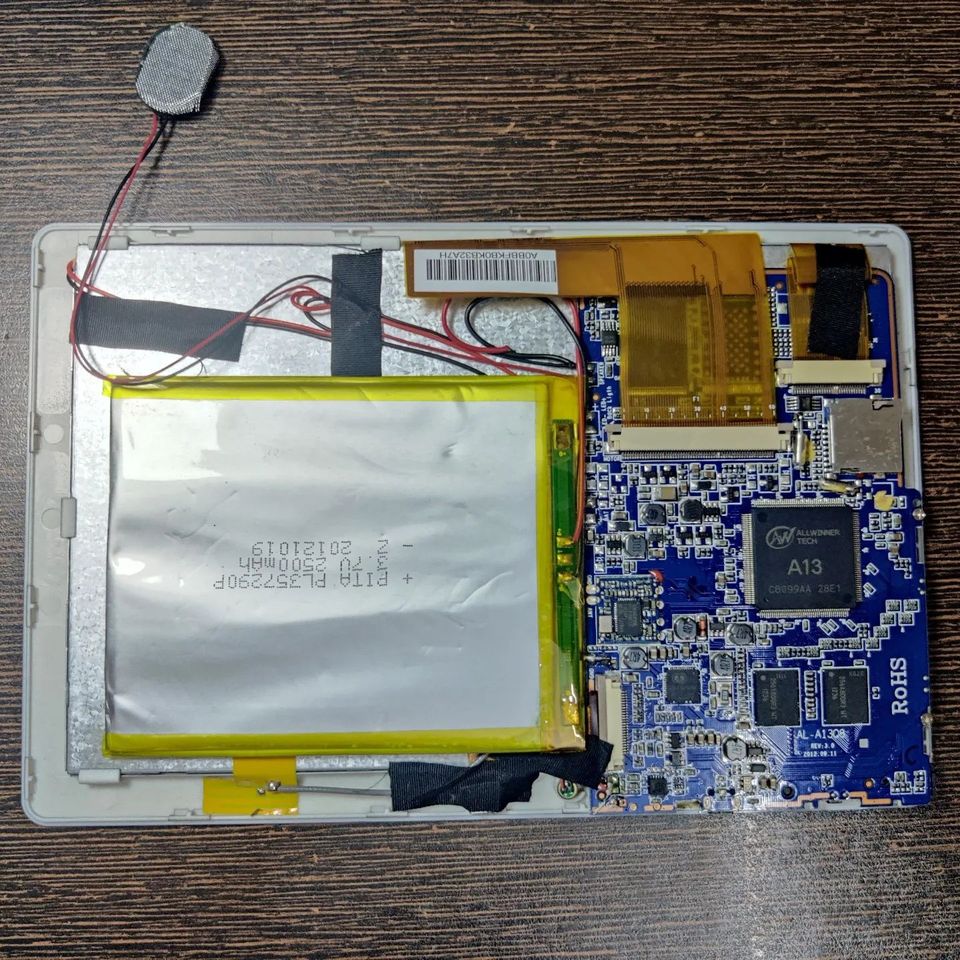
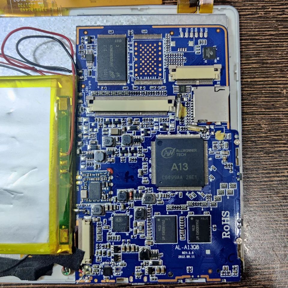
Coming to the internals and specs. It’s a capacitive 7-inch screen tablet with a front-facing VGA camera. The main processor is an Allwinner A13 SoC (ARM Cortex-A8 1GHz) which runs Android 4. It has a nifty Power Management IC in AXP209, which has 2 DC-DC converters and 5 adjustable LDOs and can support Lithium battery charging upto 1.8A. The I2C interface connects it to the main processor. The device supports WiFi connectivity with a prebuilt Realtek module, RTL8188CTV. It has a pair of 256MB RAM modules(256X8DDR3-WT, I think from HMD). This model seems to have a NAND Flash memory(MT29F32G08CBACA) of 32GB from Micron with a possibility of extending it to 64GB which remains unsoldered on PCB. SSD2532QN6 is the capacitive touch panel controller.
Well, the device is almost 10yrs old, I tried to turn it ON and it doesn’t turn ON without external power plugged in. Seems the battery is in deep discharge(2500mAh capacity) and the protection circuit is preventing charging it up even when I desoldered and tried to charge it separately. I have to remove the protection and bring it to a level then do the normal charge. There is no bulging or anything so I think the battery is fine but as always there is a risk with deeply discharged cells.
Overall the Akash project was an ambitious exercise but the hardware wasn’t upto the mark with a lot of complaints of overheating, boot crashes, software glitches, older specs etc. It never truly reached its potential of being a game-changer for students before the smartphone wave hit the country.